Tutorial: Using Haptic Feedback with Music or Audio Signals
Looking for our Haptics range? View our main Haptics hub here.
Driving ERM or LRA vibration motors with an audio signal or music is very easy with our Haptic Feedback Evaluation Kit, which provides access to the DRV2605’s “Audio-to-Vibe” function. See how to access the feature and improve the performance in this tutorial.
The Haptic Feedback Evaluation Kit is based on the DRV2605 haptic driver from TI, which features an “Audio-to-Vibe” function. This great addition to the chip makes the act of creating meaningful vibrations from audio sources, like music, extremely simple. However, there is still lots of scope to increase the sophistication (and complexity) of your system depending on how refined you want to make the vibrations.
This tutorial covers how to set the Haptic Feedback Evaluation Kit into Audio-to-Vibe mode to get users started quickly, before suggesting some more advanced options for improving the performance of their haptic audio systems. Possible applications might include a haptic metronome for musicians, force-feedback vests for music, or haptic clothing/seating for enhancing cinema or gaming experiences – each of which will want to tweak how the DRV2605 handles the audio input for optimum performance.
Getting Started
The Audio-to-Vibe feature requires you to download and install the Engineering Mode which is available here. You will also need:
- An audio file you want to play (e.g. an mp3 file or something to stream online)
- An audio driver – laptops or PC sound cards work great, mobile phones and tablets also work but vibrations may be weaker
- A cable for connecting the Haptic Feedback Evaluation Kit to the audio driver, a 3.5mm socket is installed on the underside of the Haptic Shield
- A vibration motor or LRA to play the vibrations on! Obviously, you can use the Haptic Grip, but you can also use an external motor with the Molex or screw terminal too
- A power source for the kit, if you’re uploading Engineering Mode then you can continue to use the USB port
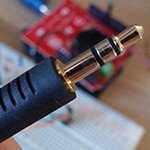
You should have easy access to most of these parts if you already own the kit, in this tutorial we’ll use a 3.5mm -> 3.5mm audio cable to connect our PC’s speaker port to the Haptic Shield.
Once the Haptic Kit has started in Engineering Mode, press select to enter the True Haptic functions. At this point, you should see your selected motor on the screen, which refers to the selected motor in the Haptic Grip. To cycle through these press the ‘PMD’ button in the top right, if you are using your own external motor you may wish to select the motor that is closest to your motor’s Rated Voltage:
| Type | Rated Voltage | Select |
|---|---|---|
| ERM | 2.7V | 304-103 |
| ERM | 3V | 306-109 |
| ERM | 4.5V | 308-102 |
| LRA | 2V RMS | C10-100 |
Once your chosen motor is shown on the screen, navigate right to the second last screen titled “Audio”. Press the Play/Pause button to start and enter the Haptic Feedback Evaluation Kit into the Audio-to-Vibe mode.
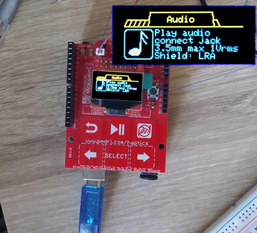
Navigate to the “Audio” menu option and press play – remember to select your actuator with the PMD button first!
Now, play your chosen audio file from your audio source and feel the vibrations played on the actuator. The performance will vary (and can be improved) depending on a number of factors, which we cover in the next section.
Limitations
Volume Levels
The vibration strength depends on two factors of the audio signal: the frequency (discussed next) and the amplitude of the signal (essentially the volume). The higher the volume, the higher the amplitude.
This means that audio devices that are designed with low voltage outputs, such as a microphone or electronic musical instrument pickups, will produce weaker vibrations. As an example, if you wished to connect a microphone and have your voice “vibrate”, then a pre-amplifier circuit between the microphone and it would help increase the voltage to a suitable level whilst containing the electrical noise.
Note that the maximum input voltage for the audio connector is 1V RMS, you should verify that your audio device does not exceed this level to ensure you do not damage the DRV2605 or Arduino.
Target Frequency Range
If you have successfully managed to feel vibrations from your audio signal, you may have noticed that lower frequencies are preferred by the DRV2605.
In fact, no vibrations are produced above ~300 Hz (your actual result will depend on the start voltage of your chosen motor). Similarly, frequencies below ~30Hz won’t drive the vibration motor either – although this is less problematic when reproducing audio signals as this is starting to reach the audible threshold for humans.
As a result, bass notes are featured far more prominently than mid-range instruments. In many instances, this is probably what you want – vibrations following the rhythmic bass than wandering melodies. However, you should note that many instruments will work across this threshold, some notes of a guitar will be picked up by the DRV2605 whilst others will not, which could result in confusing outputs.
Nonlinear Frequency Response
As a further complication to audio frequencies, the DRV2605 does not have a linear response across the entire frequency range. By sweeping a sine wave from 0 Hz to 300 Hz we can feel that vibrations are strongest around 120 Hz, with significant drop-offs at 30 and 210 Hz (based on the 306-109).
A rough guide is shown below (please note this is a subjective graph and the vibration strengths have not been measured):
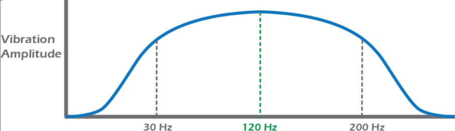
Again, this will have benefits for some users as their desired response range is likely around this peak. It is possible to focus the output on certain frequency ranges using filters, which we discuss in the improvements section below.
Stereo VS Mono
In general, this is most applicable to those looking to use music as a source, where different instruments may be mixed on the separate left and right channels. Essentially, the DRV2605 is a mono input (1 channel) but most music is stereo (2 channels), so you will need to make your stereo source output into a single channel input for Audio-to-Vibe mode.
The Haptic Feedback Evaluation Kit includes the simple circuitry to handle this for you, so the 3.5mm socket will combine the two audio channels and connect them to the DRV2605. However, if you are developing a custom circuit (as below) then this is a consideration you will need to keep in mind.
Improvements
Custom Circuits
Although the 3.5mm audio socket on the Haptic Shield makes it easy to connect to audio sources with commonly available standard hardware (and combines stereo sources into a mono signal), it is also possible to connect to the DRV2605 using the stackable headers.
This has the advantage that any custom circuits you build, for example on a breadboard, can be easily connected using jumper cables – avoiding creating a soldering a 3.5mm jack to wires that connect to your prototype circuit.
Simply connect the ground of your audio signal to the jumper marked ‘GND’ and your signal to pin D9, which provides a direct connection to pin 4 of the DRV2605 ‘IN / TRIG’. If you are using a stereo source, be sure to use the coupling circuitry outlined in the Stereo to Mono Coupling section below.
Low Pass Filters
Improve the performance of your Audio-to-Vibe system by implementing low pass filters to cut out undesirable higher frequencies and harmonics.
If you are looking to produce meaningful vibrations that coincide with a bass rhythm, then you will find some songs (and music genres in general) perform better than others. This is because some songs have instruments playing across frequencies that are similar to that of the kick drum, the DRV2605 is unable to differentiate what patterns are important from what isn’t. As a result, it might produce a fairly constant output instead of having a clear-cut feeling the motor being on and off.
Dance songs like Daft Punk’s One More Time output a good steady rhythm, acting almost like a metronome for the track. However, some rock songs like The Killer’s Mr Brightside lose their tempo amongst additional noise from the bass guitar.
Part of the issue comes a bass guitar’s low frequency (60 Hz ~ 1 kHz) appearing both inside and outside the DRV2605’s frequency range, a repeated bassline may mean that the motor never fully stops vibrating. By adding low pass filters, you can help minimise this effect by attempting to isolate the kick drums (20 ~ 100 Hz) and ‘feel’ the beat.
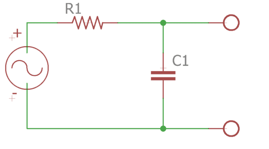
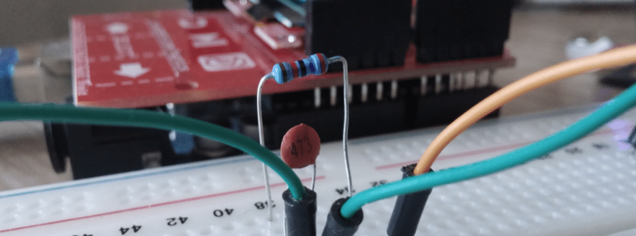
Calculating the cut-off frequency is very simple, however, because components are only readily available in certain values you may have to compromise slightly. For example, the cut-off frequency for a first-order RC lowpass filter is given:
fc=12πRCfc=12πRC
So if you wanted to create a filter that excluded frequencies above 120 Hz, but only had a 47nF capacitor, then you would need a 28,218.96 Ω resistor – which obviously isn’t a standard value! However, using standard 27 kΩ and a 1.2 kΩ resistors in series, you can create a resistance of 28.2 kΩ, which would give a cut-off frequency of:
fc=12π×28200×47×10−9fc=12π×28200×47×10−9
fc=120.08Hzfc=120.08Hz
Which is pretty good! Your success will depend on available components.
Stereo To Mono Coupling
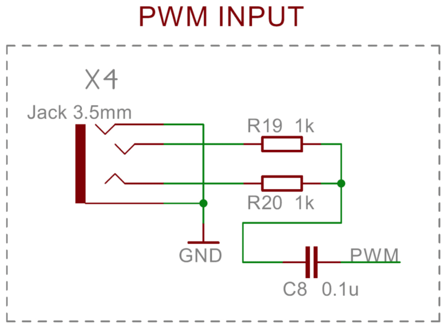
As mentioned above, the Haptic Shield includes the required components to couple both stereo channels into a single mono channel for the DRV2605.
That means you can refer to our schematics for the circuitry here, then simply copy it in your custom circuit. It uses two 1kΩ resistors and a 0.1µF capacitor:
Advanced Options
Bandpass Filters
Instead of filtering out only the unwanted high-frequency signals, a bandpass filter can filter out both the undesired high and low frequencies.
In fact, musical instruments don’t have a constant frequency when playing a single note, which is just one of the aspects of an instrument’s ‘timbre’. For example, a kick drum might have an initial attack around 100 Hz, before decaying away to 20 Hz over a short period of time. A bandpass filter can help capture the exact frequency range you want.
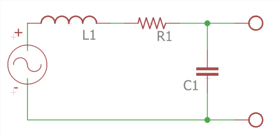
There are lots of different designs for bandpass filters, too many to cover in this article but different designs are widely available online. You can use simple passive components, such as an RLC circuit:
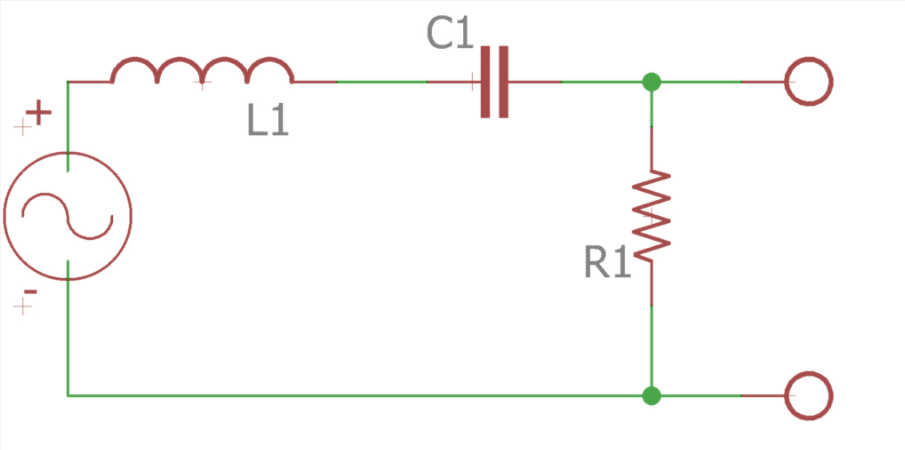
Bandpass filters are a more complicated design than the simple RC lowpass example above. You need to consider the total bandwidth and Q factor, it’s also worth noting that you can’t easily create an asymmetric response (for which you’d be better off with Digital Signal Processing discussed below). However, this limitation does make the component calculation easier, because the bandwidth B is simply the upper cutoff frequency minus the lower cutoff frequency:
B=fH−fLB=fH−fL
This is determined by the values of the resistor and inductor, where:
B=fH−fL=RLB=fH−fL=RL
You will obviously require a centre frequency for the filter, which is exactly in the middle of the upper and lower frequency:
f0=fH−B2ORfL+B2f0=fH−B2ORfL+B2
Which is determined by the inductor and capacitor:
f0=12πLC−−−√f0=12πLC
As a process for design, you may wish to:
- Select your upper and lower cutoff frequencies, then calculate the centre frequency
- Select values for L and C based on the centre frequency (you may wish to identify several “options” for the next step)
- Calculate R based on your values for L and bandwidth (which is where your options in the previous step will help you get a sensible R)
An alternative to passive circuits is using discrete op-amp circuit designs. There are even specialised programmable bandpass filters available, which have options for setting frequency control and Q factors such as the MAX263 from Maxim Integrated. These offer the highest precision and the ability to change characteristics at a later date (a discrete circuit would be set during manufacturing) which could be especially useful for users in high-end devices.
Higher Order Filters
An ideal bandpass filter would perfectly allow the desired frequencies to pass and fully reject those outside the cut-off frequencies.
Sadly ideal filters do not exist. Instead, the cut-off frequency is given as the -3dB point. This means there is a slight attenuation inside the desired range and some playback of frequencies outside the range.
By using more complex circuitry and adding more components it is possible to increase the ‘order’ of the filters, which increases the gradient of our frequency response graph – making it perform closer to the ideal filter.
There are many types of advanced filters available, including high order passive filters, active filters, and even specialist types like Butterworth or Chebyshev filters. The right choice will depend on your individual application, and how much space/cost / current you can afford to dedicate.
Digital Signal Processing (DSP)
Of course, you could add some serious capability to the system by using an Analogue-to-Digital Converter (ADC) and then performing digital signal processing in the processor (or other dedicated IC) before using a Digital-to-Analogue converter to revert it to an audio signal for the DRV2605.
Here you would be able to perform a wide range of techniques to manipulate your waveform exactly how you wanted – for example, taking a high pitched frequency and transforming it into a frequency the DRV2605 can respond to.
However, take caution so you don’t add in surplus complexity. After all, the DRV2605 Audio-to-Vibe function is essentially performing signal processing itself. At a certain point, you may be better to simply use the normal haptic modes of the DRV2605 and trigger an effect when desired, rather than converting it back into an audio signal and putting using the Audio-to-Vibe function.
Extra Assistance
At Precision Microdrives we are experienced in understanding the exact needs of an application and designing custom haptic circuits, just like the haptic-audio systems described above. If you need expert advice, then don’t hesitate to contact us and our engineers will be happy to help.

Get in touch
Speak to a member of our team.
Motor catalogue
Looking for our products?
Reliable, cost-effective miniature mechanisms and motors that meet your application demands.
Newsletter
Sign up to receive new blogs, case studies and resources – directly to your inbox.

Sign up
Discover more
Resources and guides
Discover our product application notes, design guides, news and case studies.
Case studies
Explore our collection of case studies, examples of our products in a range of applications.
Precision Microdrives
Whether you need a motor component, or a fully validated and tested complex mechanism – we’re here to help. Find out more about our company.