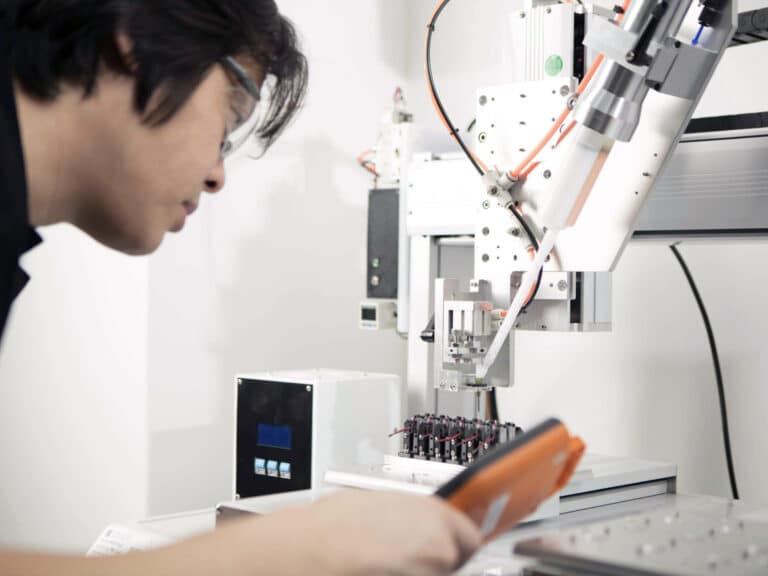
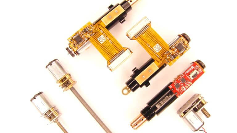
Motor mechanisms
Custom motor assemblies designed and manufactured
Trust Precision Microdrives to manage your development and manufacturing risks
Motor mechanisms are easy enough to prototype. But with many moving parts, they soon become a real challenge to mass-produce both cost-effectively and to a consistent high-quality standard. Precision Microdrives is a domain expert in this niche discipline.
Precision Microdrives offers a full turnkey service to prepare design inputs, develop a manufacturable solution and mass produce it.
- Our business is optimised for this very process.
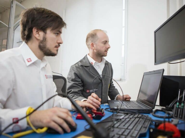
- Our design engineers in Europe are in the right place, timezone and have the right language skills to work very closely with customers to develop accurate specifications and design inputs.
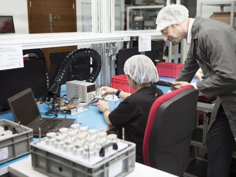
- Our product engineering team in Hong Kong have the language skills, supplier relationships and necessary design-for-manufacture experience to develop assemblies, with individual sub-components sourced from lower cost Asian supplier ecosystem.
- Our in-house manufacturing lines are located with our Hong Kong design team. This is very unusual for Asia, but it makes manufacturing optimisations, process controls and production documentation significantly easier.
Mechanism case studies
We provide mechanism solutions for all sorts of industries.
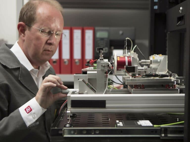
MOTOR MECHANISMS DESIGNED AND MANUFACTURED IN HOUSE
Cost effective and rigorous quality standards
PRECISION PROCESSES
Our capabilities
We can support you through the whole journey from prototype to high volume cost-effective mass production:
MECHANISM CASE STUDY
Medical diagnostics instrument
Miniature X/Z axis mechanism for medical diagnostics instrument
The challenge
Our customer, based in Germany, was undertaking a product refresh of an existing and well established bench-top medical diagnostics device. To increase sales, they wanted to adjust their business model to pay-per-test. Therefore they would have to loan or lease the instrument to doctor’s practices, instead of selling the machine outright.
To make this new model commercially viable within a reasonable time-frame, the target manufacturing cost of the bench-top instrument had to halved. The customer had previously sourced their motors from Swiss suppliers, but it was clear that a significant cost-down could be achieved by moving to an Asian supplier base.
However, manufacturing in Asia carries risks which the customer was only too familiar with, having suffered some reputational damage from earlier cost-down attempts. Furthermore, the machine had to operate with the same accuracy as before, although the machine (and mechanism) lifetime expectations were relaxed slightly to better reflect the less frequent use these instruments would experience in a doctors surgery compared to the previous market of centralised labs.
The solution
The customer engaged us to work with them on their redesign. Our involvement began with our European application engineers becoming familiar with the detailed operation of the instrument and understanding all the mechanical requirements and constraints.
From this basis of understanding, our European engineering team prepared a design inputs brief which was agreed and signed off with our customer.
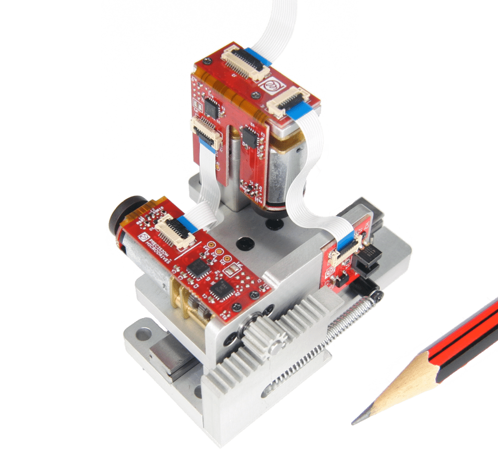
One key part of the solution was that our design inputs showed a requirement for positional accuracy in the X axis to 25μm (½ of a human hair) and in the Z axis to 12.5μm (¼ of a human hair), despite the reduction in target cost. To achieve this we integrated encoders, home sensors and custom motion controllers into the manufactured assembly.
Development proceeded as a daily triangle of progress and communication between the customer, our application engineers in London and Europe, and our product engineering and manufacturing teams in Hong Kong.
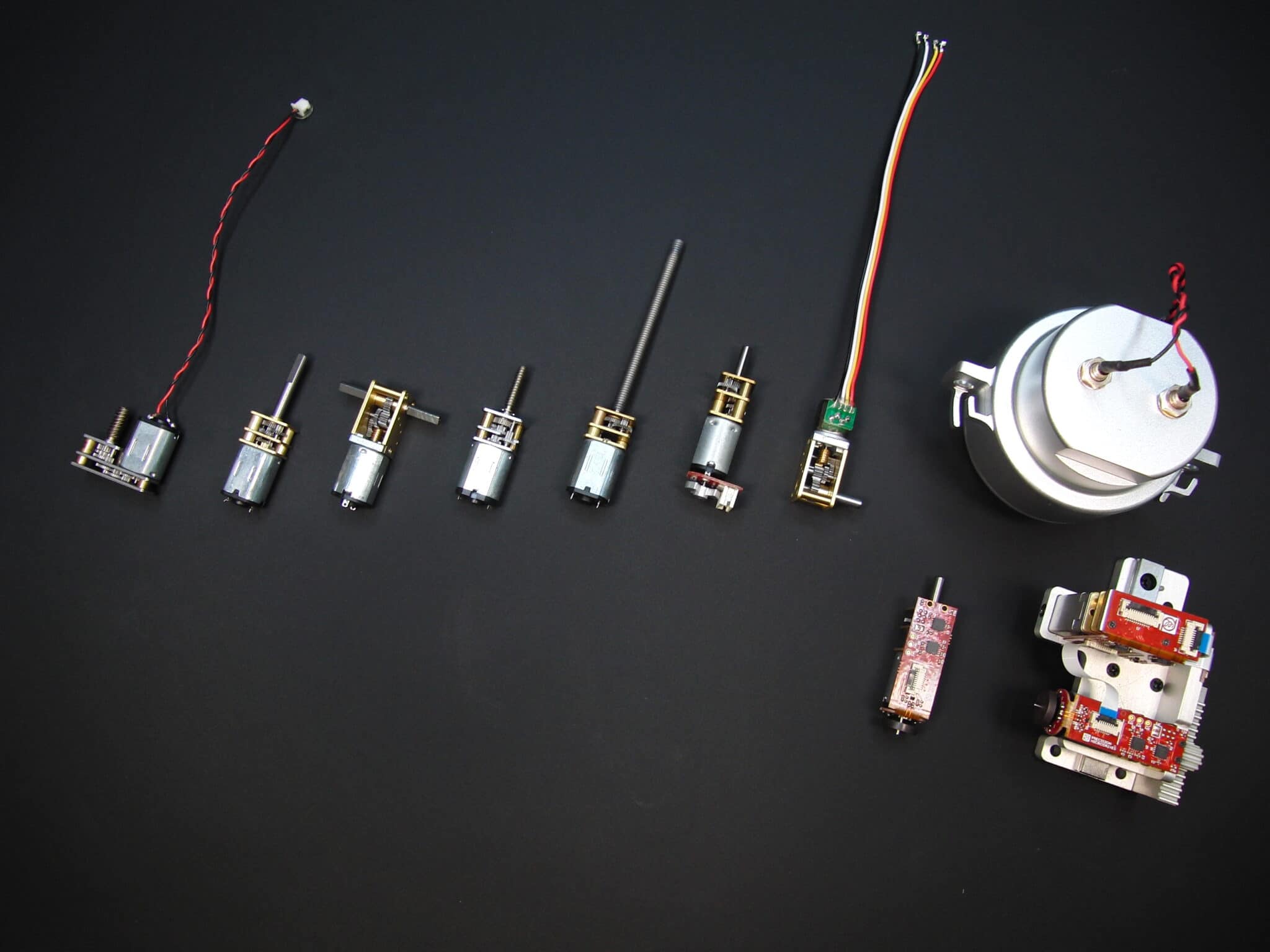
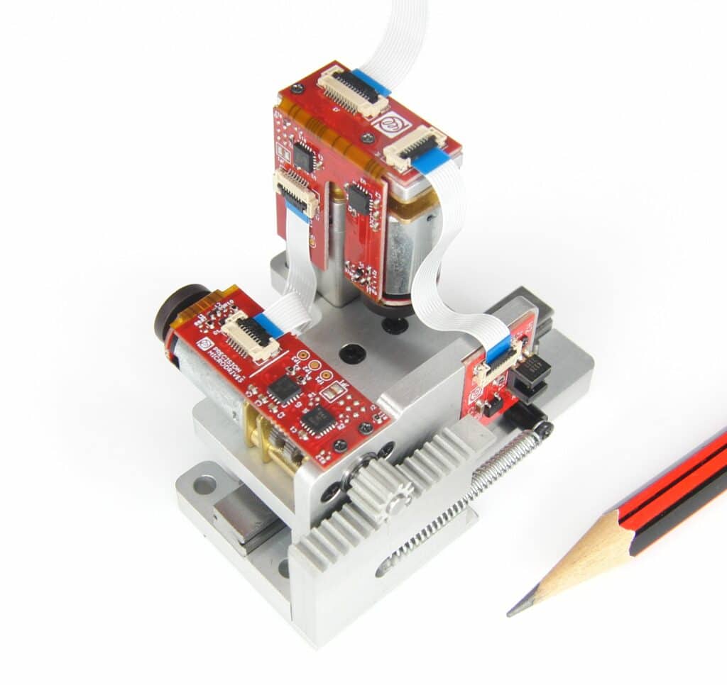
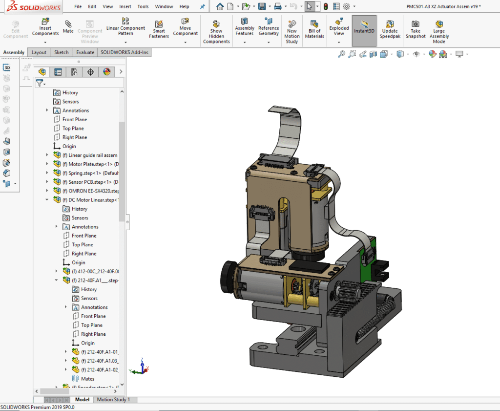
Twelve months (and several prototypes, alpha, and beta production runs) later we entered into mass production of the fully validated mechanism below.

-
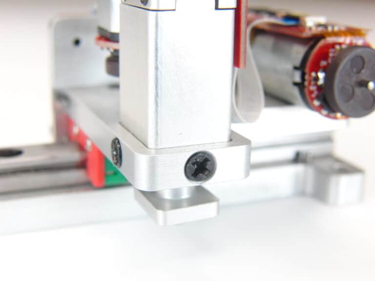
Linear slide rail
This mechanism was designed around a single aluminium plate chassis which is secured in application by fasteners from the underside.
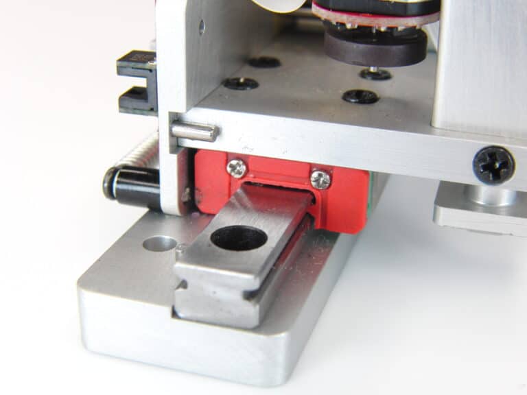
The mechanism moves on an off-the-shelf miniature linear slide rail. This was approach chosen primarily to reduce costs, but only after a careful round of engineering validation to prove that it had sufficient tolerance for the application needs.
-
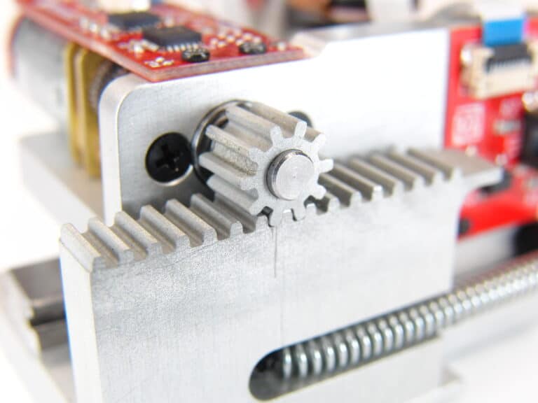
Rack and pinion
In this design the rack and pinion provides motion to the Z-axis. A 0.5 module gear design is used, with a press fit for the pinion onto the output shaft of our standard 12mm spur gear motor design.
Meanwhile, the rack component is designed to serve other purposes such as a chassis for the backlash spring, as well as a light interrupting flag for the homing sensor on one end.
The mod 0.5 gear teeth are a compromise between additional precision and gearing offered by smaller mods, and the strength and robustness offered by larger mods.
-
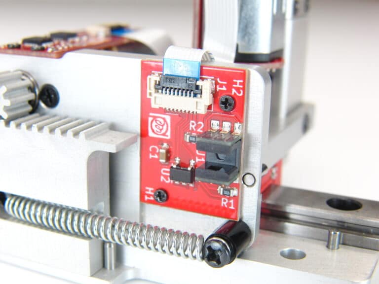
Home position sensor
In this mechanism both the X and Z axis have homing sensors, but the X-axis is most visible.
This is needed to create an repeatable positional zero point / datum for the motion controllers. In certain circumstances (e.g. power supply disruptions leading to unpredictable instrument shutdown / brown-outs), the current known position in a motion actuation may become corrupted.
Therefore upon start-up of the instrument, this mechanism will seek home and re-establish a safe motion control datum for all further motion control actuations. This internal calibration can also be commanded at any time from the instrument’s host processor / control panel.
-
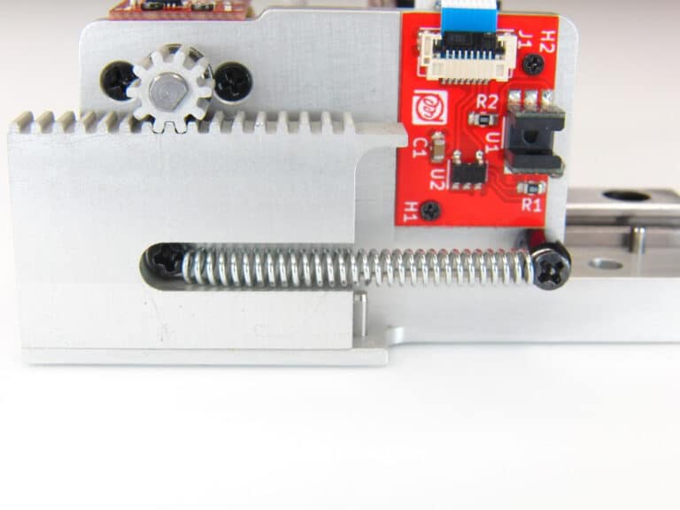
Back lash compensation
In this design, back lash compensation in the form of a simple spring, was a very cost effective way to increase the mechanical positional reliability of the linear stage. By exerting a constant force on the sliding stage, backlash is 99% eliminated in 99% of usage scenarios.
This enables this design to use lower tolerance components which are cheaper to manufacture.
-
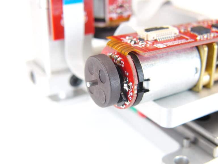
Motor encoder feedback for motion control
Motion controllers tell the motors when to move and by how much. As such, they need to know how far the motor has already moved, and how fast it is currently moving. This information or feedback, is provided by an integrated motor encoder.
In some examples we use light encoders, and in others we use magnetic ones. In this design, we have an simple cost effective AB hall sensor based magnetic encoder with 16 counts per revolution. With a 100:1 gearbox stage, that’s 1600 counts per rotation of the gearbox output shaft, which in this case is coupled directly to the rack pinion gear. That’s more than enough accuracy to deliver 0.025mm accuracy (half the width of a human hair) to the X stage at a very reasonable price!
-
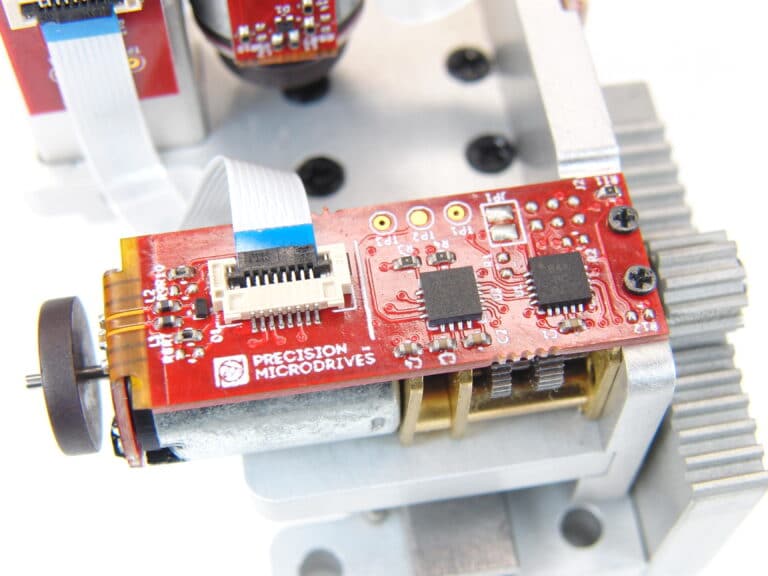
Integrated motion controller
The ‘brain’ of the mechanism are these integrated motion controllers. Microcontrollers run optimised motion control code, with various control loop algorithms, safeguards and motion profilers.
We have a number of reference designs that we can use as a basis for projects like this, which delivers cost effective proven solutions, with a short development time.
In this example, the different circuit boards are inter-connected by flat flexible FFC cables.
-
Z-axis linear motion stage
In this mechanism, once positioned on the X-axis, the Z-axis is used to open a valve on a medical test cartridge. It must extend by a precise amount, and then retract, all with minimum amount of force, and within a specified speed.
In our design the fold-back spur gearbox drives a lead screw which then extends a sprung loaded tip. The distance traveled and speed of actuation are measured by an integrated motion controller, which feeds into the Z-axis motion controller circuitry.
The Z-axis motion controller is similar in design to the X-axis motion controller, albeit with different configuration parameters to enable smooth and accurate movement.
The Z-axis linear stage is assembled as a stand-alone unit which is then secured to the mechanism chassis with 3 fasteners.
-
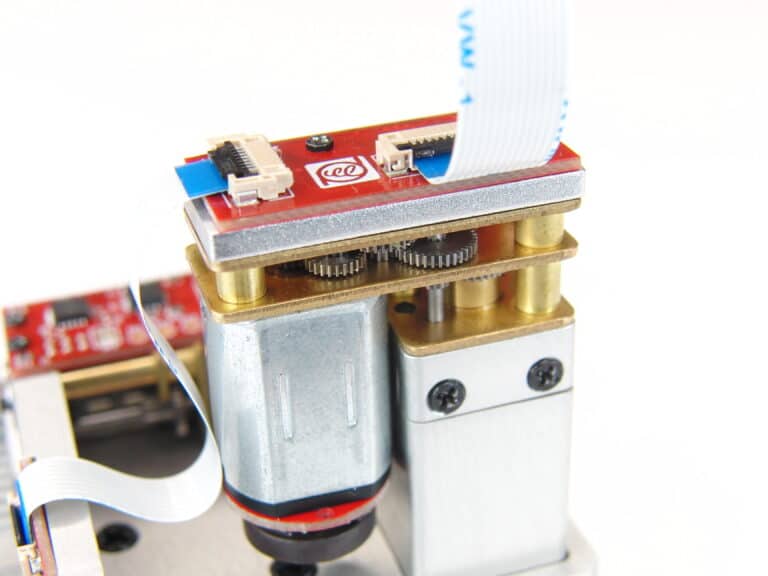
Fold-back spur gearbox
The fold-back spur gearbox is a very useful design feature, to create a dimensionally compact linear actuator. In this case that style of motor is used for the Z-axis in this mechanism.
Using the fold-back gearbox reduces the height of this mechanism by 35%, compared to a straight line gearbox, which was critical for this particular application.
On top of the spur gearbox we have designed an application facing connector, which is another flat flexible FFC cable. This delivers power and SPI communication signals between the onboard motion controller processors, and the host application processor.
-
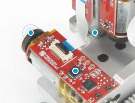
Click on the blue dots to expand!
Learn more about the features and design considerations that went into the development of this mechanism.
The results
In application, the mechanism met all the key requirements of positional performance, longevity and environmental robustness. Our assembly interfaces mechanically into the customer’s instrument chassis with ease, and our integrated motion controllers interface to the instrument’s host processor, over SPI.
The customer was able to relaunch their diagnostics instrument into the market at a lower price, and with a higher profit margin, for those customers wanting to purchase it outright. They were also able to launch a new pay-per-use diagnostics model to a new set of customers. In this model, the instrument was loaned, and the end-users paid a higher price for each test assay.
HOW CAN WE HELP?
The Precision Microdrives Advantage
Custom Assemblies
Longevity testing
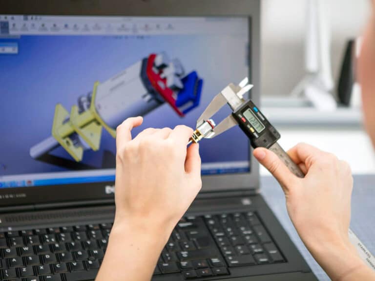
Mechanism design
Engineering confidence
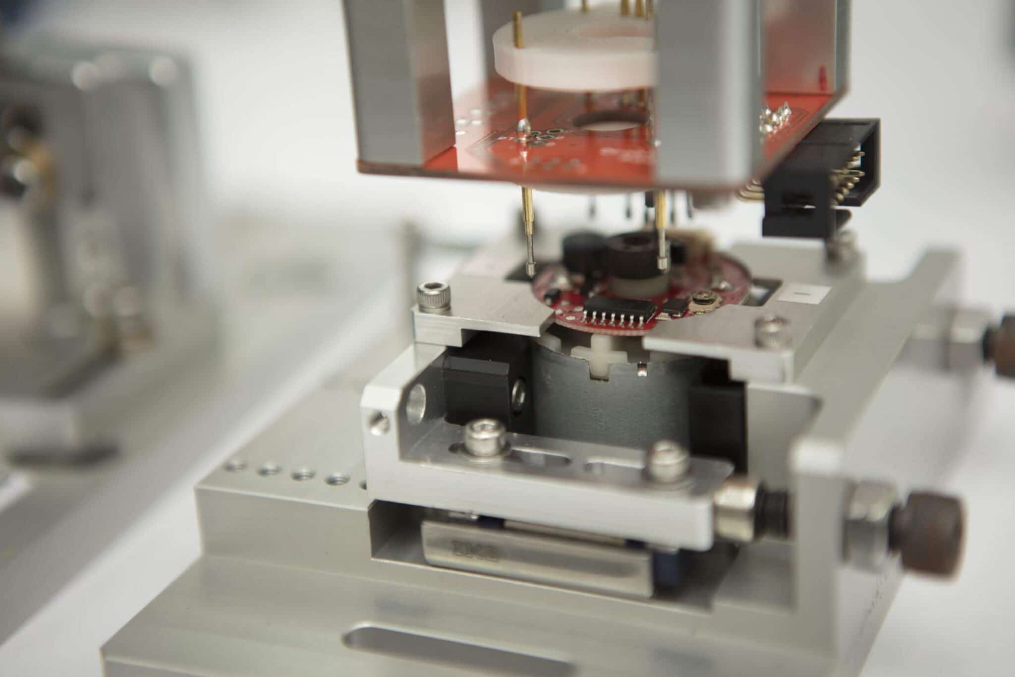
In-house production
Full testing validation
MECHANISM CASE STUDY
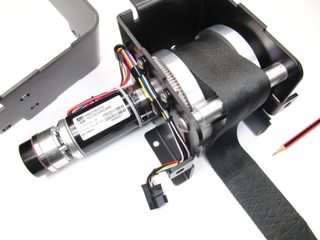
Heavy duty mechanism for hospital patient lift
The challenge
In this project our customer manufactures hospital and mobility equipment in the USA. They were designing a new hospital patient lift that was capable of lifting 350kgs from an overhead gantry. The lift had to be low voltage so that it could be powered by either a mains / line connection, or a portable and 24v rechargeable battery pack.
The lift had to power-off in a safe state. That means that in the case of a power failure, the patient lift would lock, and hold the patient in place until the power was reconnected, or a manual release process was used by hospital staff.
Since this product was an upgrade over an existing model, the customer wanted to introduce new motion control features such as pre-set / memorised lift patterns. We suggested that in addition, mechanism wear could be reduced by introducing motion profiling to reduce the acceleration loads during motion.
The mechanism had to be housed in a robust steel enclosure with index and location features, as well as fastening / fixing points for the end application.
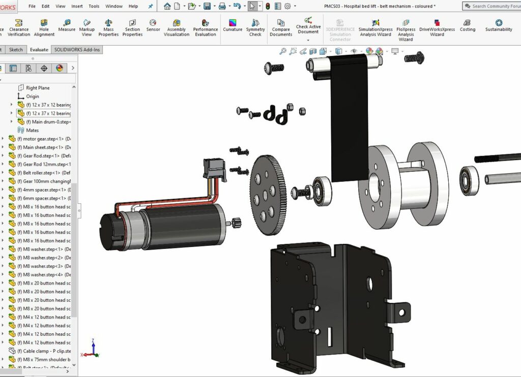
The solution
We started with some CAD data from the customer’s engineering team. This showed the envelope at our disposal and the location of the load bearing fastening points.
The customer also gave us details of the woven strap to be used to connect the lifting drum with the hoist point and a target lifting speed. The woven strap was very similar in construction to a car seatbelt and we worked out the necessary geometry of the lifting drum, gear ratios and motor output power.
With that settled, we were then able to start working on integrating the lifting drum and its axel points, with the enclosure which was to be manufactured from a punched and folded metal sheet. By using the axel points to add strength to the frame enclosure, we saved parts and cost. Strength calculations and simulations were performed on the final structure and were shown to have a sufficient safety margin. One particular consideration was high loads caused by a sudden deceleration / emergency halting whilst in the middle of a lift.
Given the volumes, the most appropriate method for manufacturing the aluminium lifting drum was bolting together several turned CNC components, with a steel gear bolted to one of the outside faces. We designed a mod 1 gear train, coupling a 52mm high torque coreless motor to the lifting drum.
The motor itself had to be fitted with an encoder for motion control, and a failsafe electro-magnetic brake. This would lock the motor and therefore lifting drum in the case of a power failure.
By this point, the design was 95% complete, and we turned our attention to the details. There were a number of indexing points that the customer wanted integrated into the frame enclosure. By this point, we also had a number of drive and control lines that needed to be terminated in an 8-way connector. These lines also had to be routed and were secured by p-clips around the edge of the frame enclosure.
-
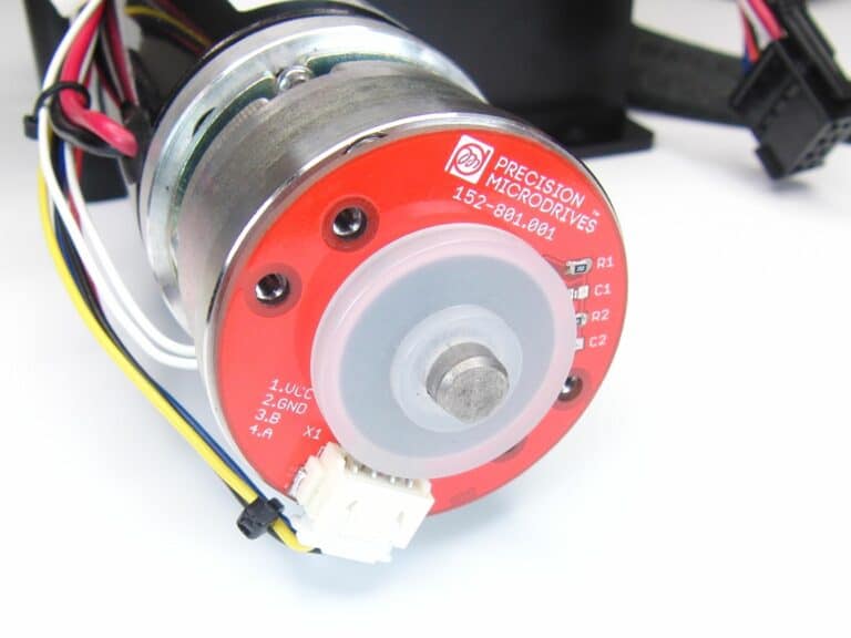
Motion encoder
Our mechanism was fitted with a reliable AB optical encoder, to provide speed and positional feedback signals back to the motion controller. This design had no obvious index point, since the hub has to make multiple rotations. Therefore, a positional calibration technique was adopted where the motor was run slowly, and current measurements were used to detect an end of travel stall point.
-
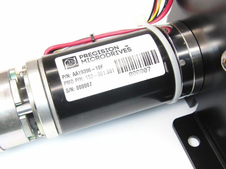
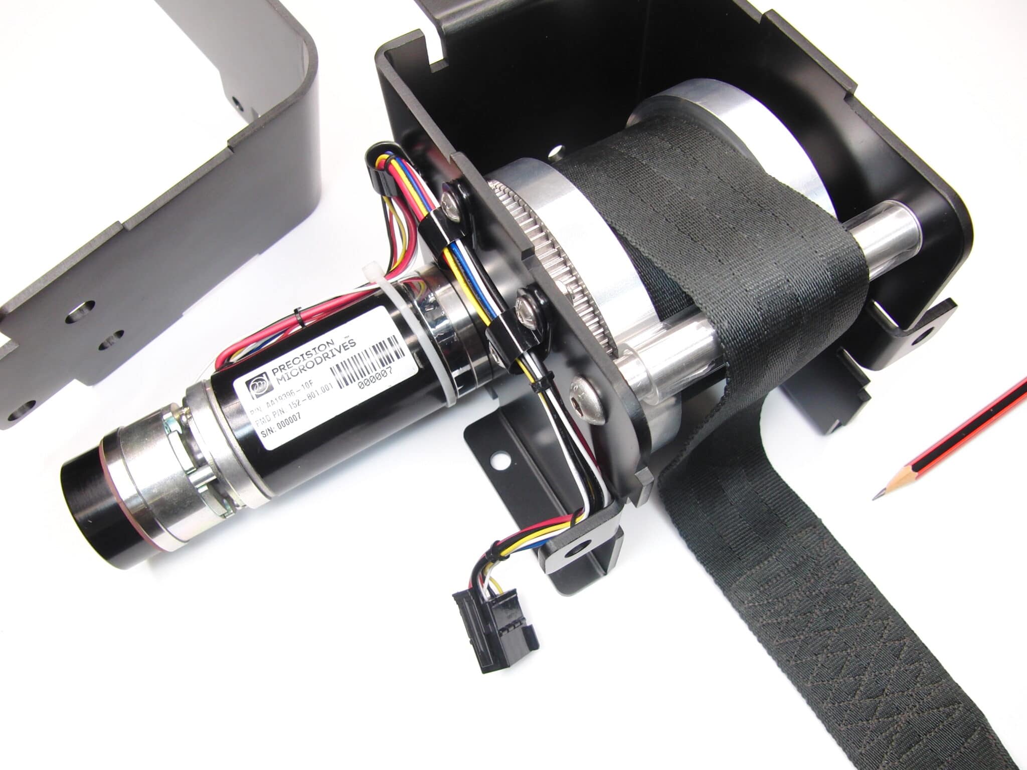
High torque coreless motor
We developed a 52mm coreless motor for this application, offering a high torque in a compact package. This design is also able to dissipate any motor heating that might arise from extended use of the lift.
The motor was designed with a double ended shaft. One end is fitted with a mod 1 pinion gear which meshes with the winding drum, and the other end connects to the electromagnetic brake and motion encoder.
-
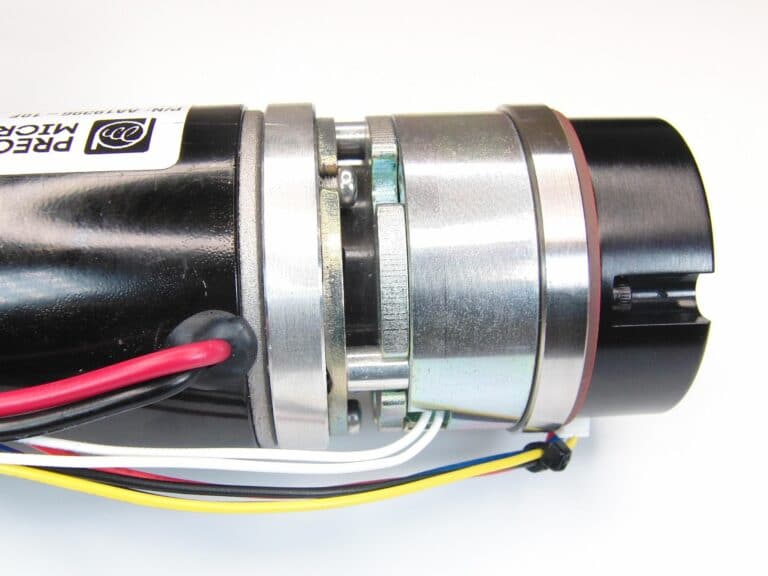
Electromagnetic brake
The rear shaft from the motor is manufactured with a flat, creating a D-shaft that connects with the electromagnetic brake, fitted to the rear of the motor. This brake requires power to release, meaning that in the case of a power failure, the brake will engage automatically.
This is added to allow a failsafe mechanism, so that patients aren’t accidentally left to fall in the case of a power cut.
-
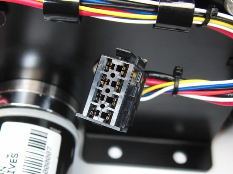
Custom wiring harness
Connecting our assembly to the customer’s application is done electrically by the use of a heavy duty 8-way connector. The arrangement of pins within the connector was chosen carefully to minimise EMI cross-talk from the motor power lines to the encoder signals.
-
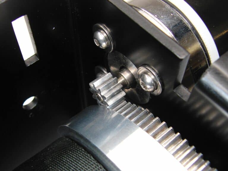
High strength geartrain
The front shaft of the motor is fitted with a mod1 steel pinion gear which interfaces with a large steel gear bolted to the side of the wining drum.
Running at target speed, and with appropriate lubricant (added during final assembly by the customer in this project) the resulting geartrain is efficient, quiet, and reliable. It will not need to be serviced again during the lifetime of the product.
-
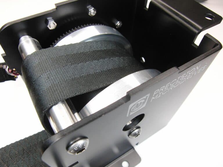
Belt winding drum
The belt winding drum is manufactured from 3 pieces of turned aluminium and revolves around two internal bearings that sit on a steel shaft. The steel shaft is bolted to the enclosure / frame adding structural rigidity.
A mod1 gear is bolted to the side, and the belt is wound on, anchored in place with a bolt.
The belt runs over a plastic tube bearing sitting on another steel shaft which adds further structure to the enclosure / frame.
-
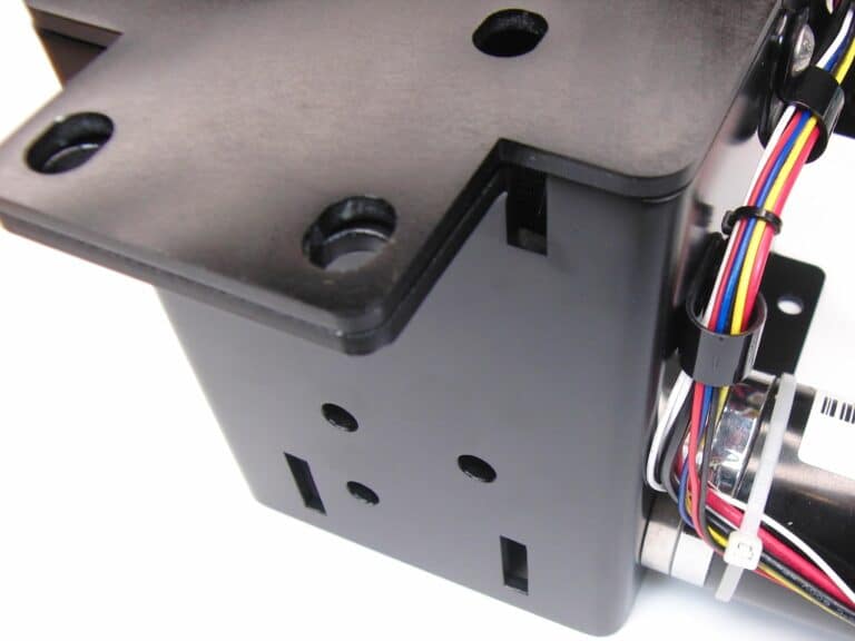
Custom features for application integration
At the start of the project, the enclosure envelope was defined, and fixing point geometry agreed.
Through the development phase of project, the customer requested a series of features to be integrated into the enclosure frame. Most of these were locating features to aid final assembly of the lift, and a few others were used as points for routing the customers wiring looms.
-
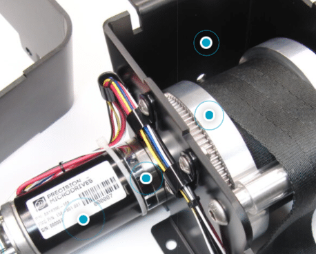
Click on the blue dots to expand!
Learn more about the features and design considerations that went into the development of this case study mechanism.
The results
The customer spent six months putting our mechanism through rigorous in-application testing, whilst we simultaneously undertook a program of component validation and testing. With all tests complete and fully passed, we proceeded into mass production against the customer’s schedule.
The customer’s product update was received well in the market and sales increased 36%, which was a great win for both us and our customer. In addition, giving the design authority role for the lifting mechanism to our team enabled the customer to focus their internal engineering team on other innovations that differentiated them against their competition.
HIGH QUALITY RELIABLE MECHANISMS
Industries we serve
Designing mechanisms for a wide range of applications


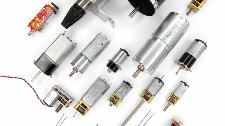
MOTORS & MECHANISMS
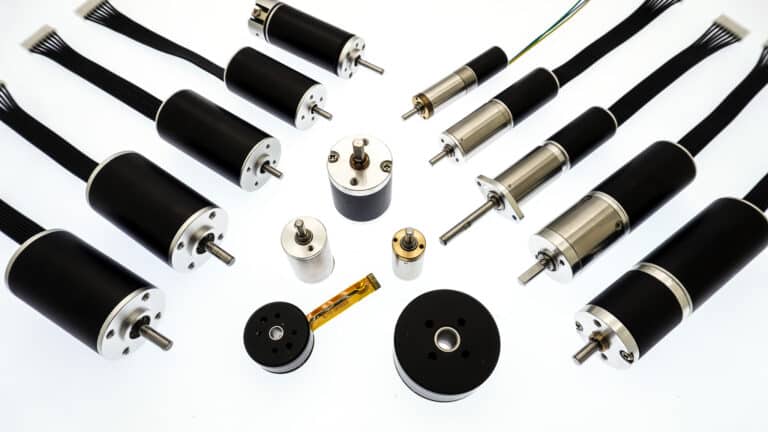
Precision products
Verified and reliable precision motors, perfect for your application.
-
Brushless Motors
We offer a comprehensive range of DC brushless motors in both slotted and slotless (high torque and negligible cogging) designs,
View Page
-
Vibration motors
With every vibration and haptic technology covered, we’ll help you select the best vibrating solution for your application.
View Page
-
DC motors
Iron-core, coreless and brushless DC motor technologies in a wide range of form factors and sizes, with off the shelf
View Page
-
DC gear motors
Building on our range of DC motors, we integrate spur and planetary gearboxes, from 6mm to 60mm frame diameters.
View Page
-
Haptic feedback
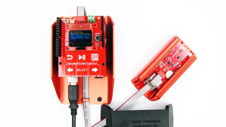
Practical and reliable, low noise and high quality haptic feedback solutions for all types of application user interface.
View Page
-
Linear actuators
Precise, reliable and highly customisable linear actuators designed for a wide range of industrial, commercial and medical applications.
View Page
Our customers
We’re proud to support all customers large and small. Here are a few of our customers that we have designed and manufactured motors and mechanisms for.


Discover more
Resources and guides
Discover our product application notes, design guides, news and case studies.
Precision Microdrives
Whether you need a motor component, or a fully validated and tested complex mechanism – we’re here to help. Find out more about our company.
Case studies
View our past projects with examples of various different applications utilising custom-made motor and mechanism solutions from Precision Microdrives.