When LRA’s don’t behave as expected (Part 1 of 2)
This blog post is part one of a 2-part series. Part one is a quick recap of how LRAs work and how they are driven by dedicated driver ICs. Part 2 is about what happens when the LRAs don’t work entirely as expected with selected driver ICs, how to diagnose this, and what to do about it.
Introduction
Linear Resonant Actuators (LRAs) are becoming ever more popular in haptic applications. As an alternative to Eccentric Rotating Mass (ERM) vibration motors, they have several distinct advantages: they provide a faster response, a higher vibration efficiency, and offer a longer lifespan. In conjunction with the necessary driver, they also offer more advanced haptic effects.
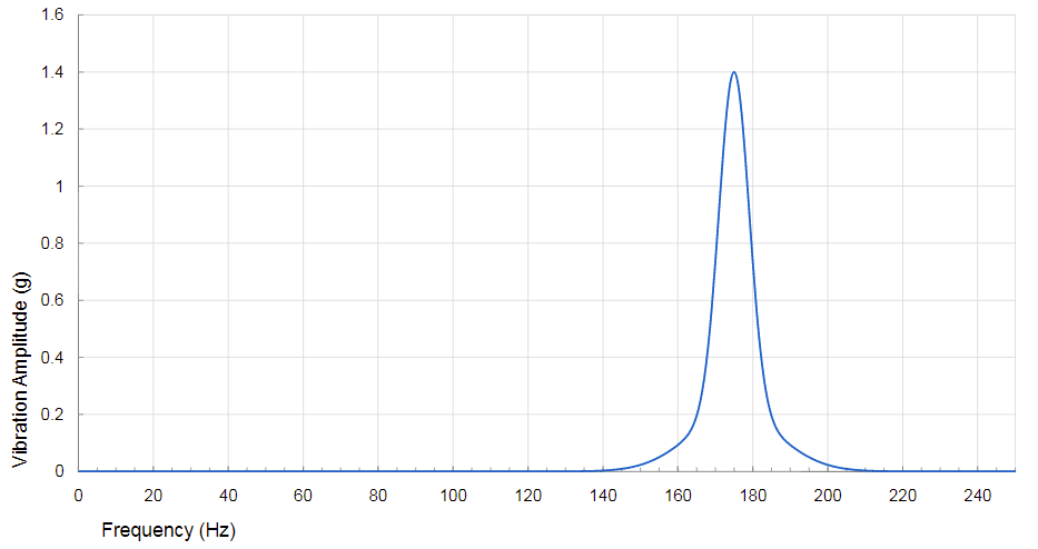
LRA motors are driven by an alternating current (AC) comprised of a specific peak amplitude and frequency. Both values are intrinsically related to the construction of the motor. When the LRAs are driven with a frequency different to their resonant frequency, the performance, and therefore the efficiency, drops dramatically. Figure 1 gives a visual perception of how a small variation in the resonant frequency can affect the amplitude of the vibration. Thus, LRAs can vary their vibration amplitude through the driving voltage supply, but the vibration frequency must be set to match the LRA’s resonant specifications for optimal performance.
LRAs are typically driven in one of two ways. The first option is to use a sine wave from a signal generator circuit; the second involves the use of a dedicated IC. For evaluation and prototyping purposes, using a signal generator can be an easy and quick way to evaluate the motor performance, however, when looking to a DFM solution, the implementation of a dedicated IC becomes a must.
Several companies produce driver ICs compatible with Precision Microdrives LRAs. For the purposes of the case study in part 2, a customer had coupled our C10-000 LRA with the Texas Instruments driver DRV2603.
Auto-Resonance Detection
The exact resonance frequency is not a fixed value and can vary by a small percentage. Factors such as the mounting, orientation, environment, and the age of the LRA can affect the resonance frequency (as can the small part-to-part variation across manufactured batches). The C10-000 is rated at 205Hz. Accordingly, we can expect the LRA resonant frequency to always sit within a range of 200Hz to 210Hz.
We can see in Figure 1 that with the same drive signal, a frequency shift of 5Hz from the resonance frequency will result in a vibration amplitude drop of nearly 40%. Therefore, it’s important for the driver to track the resonance frequency in real-time, to allow the LRA to continually maintain the peak output amplitude. Note, it is only possible to adjust the frequency of the signal cycle-by-cycle using an IC driver.
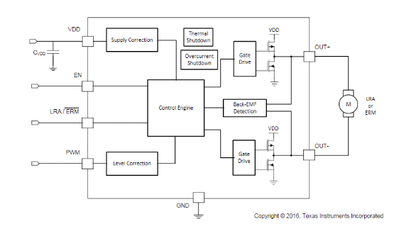
There are several drivers that incorporate features to determine the resonance frequency. In our example, the Texas Instruments DRV2603 was used, but it has a typical driver architecture, as shown in the block diagram below.
There are several factors that should be taken into account when determining which driver will work best with any given LRA:
- Frequency tracking range for LRA (the LRA resonant frequency must be within that range)
- Steady-State Output Drive
- Power consumption
- Haptic sharpness
- Cost
The DRV2603 accomplishes this resonant frequency tracking function by actively sensing the back-EMF (BEMF) voltage. The BEMF is the voltage that opposes the current which induces it. In the case of an LRA, it is a voltage generated whose current flows in the opposite direction of the supply voltage.
The BEMF value depends mainly on the physical construction of the motor and its speed. As the physical construction of the LRA is a fixed variable for each motor, we can assume that BEMF is a reliable variable to measure the position of the motor.
Conclusion
As seen here, the use of a dedicated IC driver is a must when using LRAs in production. We receive many enquiries from customers regarding the implementation of LRAs and often, the selection and setting of the appropriate driver, and even the driver settings, makes a big difference on the output. To get the best performance from any LRA, it’s worth investing some time with the supplier to correctly match the driver set-up. At Precision Microdrives we’ve troubleshot a lot of implementations – some well-architected and others not so well thought out. Either way, we’re here to help.
In part 2 of this multi-part post, we will cover a real case study which was something of an edge-case, where the LRA, the driver settings and the mounting conditions turned out to be incompatible. A thorough investigation was carried out by our quality team as they debugged this situation, and we want to share some of these findings to advise our customers.

Get in touch
Speak to a member of our team.
Motor catalogue
Looking for our products?
Reliable, cost-effective miniature mechanisms and motors that meet your application demands.
Discover more
Resources and guides
Discover our product application notes, design guides, news and case studies.
Case studies
Explore our collection of case studies, examples of our products in a range of applications.
Precision Microdrives
Whether you need a motor component, or a fully validated and tested complex mechanism – we’re here to help. Find out more about our company.