AB-003
Driving linear resonance vibration actuators
What are linear resonance actuators?
Most vibrating motors in our product range are DC Eccentric Rotating Mass (ERM) motors which are produced with an offset weight attached to the shaft. These are available in commutated pager motor form factors as well as brushless, and ‘coin’ types which use the ERM principle. When the weight rotates the centripetal force of the weight causes a vibration. The ERM is crude but it works. A recently developed alternative to the ERM is the Linear Resonance Actuator (LRA).
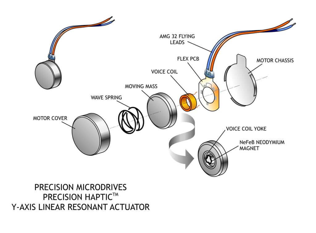
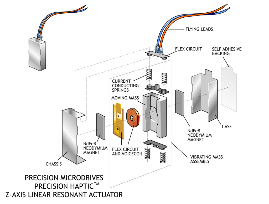
LRAs use a movable mass, permanent magnet, voice coil and spring to generate vibrations. The voice coil produces a magnetic field which interacts with the permanent magnet, causing it to move and by doing so, compresses or stretches the spring to which it is attached. The drive signal needs to alternate the direction of current (i.e. it’s an AC signal) and hence the magnetic field to make the permanent magnet oscillate back and forth with the spring. The moving mass is attached to the magnet, and it is the moving of the mass back and forth that generates the vibration.
There are several reasons why LRAs may be preferred haptic vibrators in some designs:
- LRA’s have a longer lifespan as they do not have internal brushes which are susceptible to wear. This makes them effectively brushless, although the springs will fatigue over time,
- LRA’s typically offer improved haptic performance with short lag and rise times, an important consideration for simulating short duration – high frequency tasks such as keyboard switches for typing,
- They consume lower power than ERM equivalents,
- Compact size (though may not be desired as it is related to maximum vibration amplitude),
- The input signal’s amplitude and frequency are independent of each other, allowing the input to have a more complex waveform than with an ERM. This can produce a ‘richer’ user haptic experience.

Get in touch
Speak to a member of our team.
Motor catalogue
Looking for our products?
Reliable, cost-effective miniature mechanisms and motors that meet your application demands.
Replacing An ERM Vibration Motor With An LRA
Mostly it is not possible to directly swap an ERM motor with an LRA vibrator. As you may have noticed above, we already mentioned that the input signal to the LRA has to alternate, i.e. it needs an AC drive signal.
AC drive signals can have a frequency and an amplitude. The higher the amplitude the greater the vibration output for a given frequency. However, the frequency of the drive signal is a very important factor. The LRA has a resonant frequency at which the input signal should operate, to maximise the vibration generated.
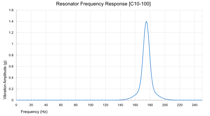
Vibration performance drops off significantly when the input signal frequency is moved too far from the resonant frequency, as can be seen in the diagram below. Our datasheets state the resonant frequency of our LRAs and have a typical performance ‘bode plot’ which shows the amplitude vs frequency; e.g. the bode plot below is taken from our C10-100 LRA.
Since most applications for LRAs will have a single power supply, generating an AC drive signal is not trivial. Whereas one can use a single MOSFET with a microcontroller to drive a DC motor, for the LRA the easiest option is to use a dedicated driver IC.
That said, some haptic drive ICs are capable of outputting to both an ERM and an LRA, so in these cases / existing applications, it may be a simple configuration adjustment. Often, if the device can drive an LRA it can drive an ERM, however not all ERM drivers can produce the AC output for the LRA.
Several driver ICs are available as an independent chip, and some companies have vertically integrated the haptic driver capability into a touchscreen or other input device drivers. Below we’ve summarised a few of the more readily available models on the market.
Stand-Alone LRA Drivers
Texas Instruments – DRV8601
Texas Instruments (TI) have a haptic division, who have produced a driver for both ERMs and LRAs. Aimed primarily at portable electronic devices the DRV8601 can accommodate a range of supply voltages (and therefore battery types). It’s controlled by a PWM signal, the frequency of which relates to the resonant frequency of the LRA. It uses the duty cycle of the PWM to change the amplitude of the LRA’s vibration.
A typical driver schematic is shown below.
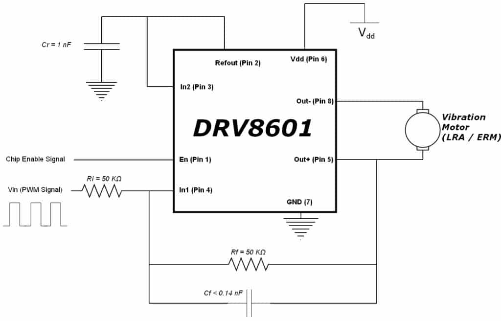
Component values should be configured as follows:
Step 1
Set 𝑉𝑃𝑊𝑀(𝑃𝑖𝑛4)=𝑉𝐷𝐷(𝑃𝑖𝑛6)This gives you greater haptic control as you can temporarily stop the LRA without powering down the chip. How does it work? The DVR8601 has an internal regulator that sets Refout to VDD / 2. Then, given that In 2 (Pin 3) and Refout (Pin 2) are connected:𝐼𝑛2(𝑃𝑖𝑛3)=𝑅𝑒𝑓𝑜𝑢𝑡(𝑃𝑖𝑛4)=𝑉𝐷𝐷2and if:𝑉𝑃𝑊𝑀=𝑉𝐷𝐷
then:𝑉𝑃𝑊𝑀2=𝑉𝐷𝐷2
When you set the PWM to a duty cycle of 50%, its average voltage is given as:𝑉𝑃𝑊𝑀∗50%=𝑉𝑃𝑊𝑀∗0.50=𝑉𝑃𝑊𝑀2=𝐼𝑛1(𝑃𝑖𝑛4)now:𝐼𝑛1(𝑃𝑖𝑛4)=𝐼𝑛2(𝑃𝑖𝑛3)The output of the DVR8601 (Pins 5 and 8) is given as:𝑉𝑜𝑢𝑡=2∗(𝐼𝑛1–𝐼𝑛2)∗𝑅𝑓𝑅𝑖∗11+𝑠𝑅𝑓𝐶𝑓Where s is the Laplace Transform Variable. So we can see that when VPWM is at a 50% duty cycle, it is equal to VDD / 2 and the two inputs In 1 and In 2 are equal, and the output voltage is zero. This stops the LRA from vibrating but can be quickly activated by adjusting the PWM duty cycle.
Step 2
Set 𝑅𝑖=𝑅𝑓=50𝑘ΩThis sets the gain of the circuit to 1 as:𝐺𝑎𝑖𝑛=𝑅𝑓𝑅𝑖
Texas Instruments suggest resistors in the range of 20 kΩ to 100 kΩ for stable operation, we’ve chosen 50 kΩ. However, you may want to revise your selection after reading the next section on capacitor 𝐶𝑓.
Step 3
Set 𝐶𝑓<14.4𝑛𝐹
This too gives you greater haptic control because it allows you to control the amplitude of vibration by adjusting the PWM duty signal. The (optional) feedback capacitor in parallel with Rf forms a first-order low-pass RC filter. This means the output voltage is a function of the average PWM voltage, which can be controlled with the duty cycle. An important consideration when using the RC low pass filter is that the cutoff frequency must be higher than the resonant frequency of the LRA. As an example, we’ve chosen our C10-100, which has a resonant frequency of 175 Hz and typically shows little vibrational amplitude above 220 Hz. Using 220 Hz as our cutoff frequency, and 50 kΩ for Rf, we can solve the following low pass filter equation for Cf:𝑓𝑐>12𝜋𝑅𝑓𝐶𝑓𝐶𝑓<14.4𝑛𝐹
Step 4
Set 𝐶𝑟=1𝑛𝐹This capacitor is to remove any unwanted noise from the internal regulator, although larger values increase the turn-on time. Texas Instruments recommend using a 1 nF, X5R dielectric or better, capacitor.
Step 5
Finally, make sure the input PWM signal has a suitable frequency for the Linear Resonant Actuator. The duty cycle should be varied symmetrically above and below 50% (i.e. ± 25%). This could be either a square wave, or one could use a look-up table in the driving microcontroller to produce more complex signals.In the example below, the drive signal has a frequency of 1400 Hz because there are 8 samples per cycle. This produces a square wave at 175Hz, which would work well for the C10-100 (it has a 175Hz resonant frequency). The PWM signal in the example alternates between 25% and 75% duty cycles.
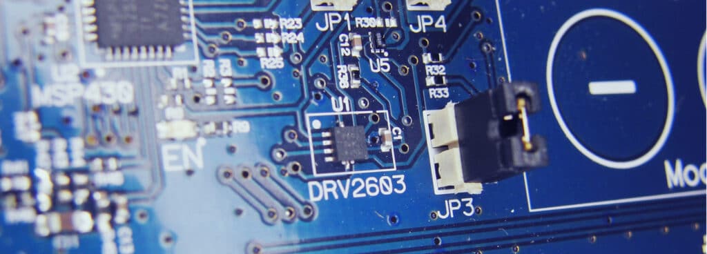
Texas Instruments DRV2603
Texas Instruments have released a new generation of chips aimed at driving LRAs, and they include some pretty impressive features.
The most significant of which is the Auto Resonance Detection for the LRA. This solves many of the problems facing linear resonant actuators:
- LRAs must be driven at their resonant frequency – even a few hertz off will dramatically reduce performance
- The resonant frequency will change depending on what it is mounted to, the climate, age of the product, and will even be slightly different between different LRAs from the same manufacturing batch
- When using different actuators the frequency of the drive signal must be changed, meaning the processor code is LRA dependent, making it less flexible
With auto resonance detection the processor can use a wide range of PWM signals, with the duty cycle adjusting the vibration amplitude. The LRA will always be driven right on its resonant frequency regardless of its environment, and the actuator can even be swapped for one of a different resonant frequency with no change to the control circuit.
For example, we have two LRAs that vibrate in different axes:
- C10-100, Y-Axis, Resonant Frequency = 175 Hz
- C13-000, Z-Axis, Resonant Frequency = 205 Hz
If you wanted to compare them to see which vibration direction worked best for your product, you would need to change the frequency of the drive signal. This would require editing the code in the processor – which you may not be familiar with or may not have access to development tools. When using the DRV2603 you can simply swap the LRAs over.
In fact, you do not need to calibrate the input frequency at all, the DRV2603 will handle it automatically.
There are a host of other features, including automatic braking and fast startup time, and it can even support ERMs too which makes it excellent for prototyping. If you’re interested in testing it out we suggest you look at their evaluation kit on the following link (with one of our LRAs):
CORERIVER Semiconductor Co. – RingCore210 Family (RC210-QF16IP / RC210-DF10IP)
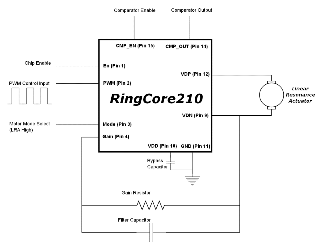
The RingCore210 chips are similar in performance, to the ‘QF16IP’ or ‘DF10IP’ packages. They can both drive either ERMs or LRAs, one pin sets the mode of the device accordingly. They are driven with PWM drive signals, but for LRAs, the frequency of the output is determined by the value of a capacitor between the negative output pin and the GAIN pin. This allows for resonant frequencies to be set anywhere between 80 Hz and 390 Hz.
The ringcore schematic is shown below:
Integrated LRA Drivers
SEMTECH – SX86- Family – Resistive Touch IC / Haptic Driver
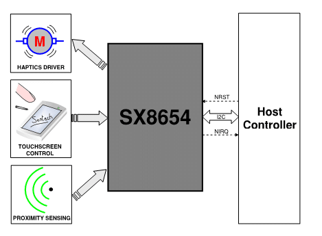
Many chips from Semtech’s range have haptic drivers and an interface designed to process the input from resistive touchscreen devices. The major difference between models is the inclusion of a proximity sensor system, or the ability to handle multitouch inputs. They can drive the ERM or LRA using either an external PWM or by writing the desired vibration level to a register using the I2C serial interface. A simple configuration value changes the chips from operating with an ERM or LRA, with the duty cycle of the PWM changing the amplitude of vibration.
Maxim – MAX11810/MAX11811 – Capacitive Touch IC With Haptic Driver
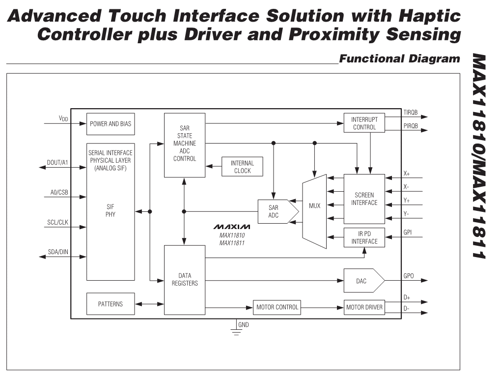
Maxim’s two devices are capacitive touchscreen interfaces with integrated proximity sensors and a haptic controller and driver. The difference in models is that the MAX11810 uses an SPI interface, while the MAX11811 uses an I2C interface. The haptic controller and driver are separated because the controller can also produce a PWM signal for use with piezo haptic devices. Instead of accepting an input signal to drive the haptics, the chips use their own internal waveform generator to control the LRA or ERM through a serial interface.
Conclusion
This application bulletin presented a review of a linear resonant actuator (LRA) vibration motor drivers and detailed how to use the most available one – the DRV8601 from TI. Remember to take a look at our other application bulletins which may cover different aspects of this subject. You can always find these on our vibration motors application note page.
Newsletter
Sign up to receive new blogs, case studies and resources – directly to your inbox.

Sign up
Discover more
Resources and guides
Discover our product application notes, design guides, news and case studies.
Case studies
Explore our collection of case studies, examples of our products in a range of applications.
Precision Microdrives
Whether you need a motor component, or a fully validated and tested complex mechanism – we’re here to help. Find out more about our company.