How to Drive a Vibration Motor with Arduino and Genuino
Looking for our Haptics range? View our main Haptics hub here.
Looking to drive a DC vibration motor using an Arduino or Genuino? In this article, you’ll find simple circuitry, suggestions on using Pulse Width Modulation (PWM), and an example code to download.
Microcontrollers are used with virtually every vibration motor application. Whilst some industrial applications may want vibration motors to run continuously (where we would recommend a brushless vibration motor), in most cases vibrations are desired at specific times and for specific durations. As prices and size of chips have decreased, it has become incredibly simple to access and implement microcontrollers. This guide will show you just how easy it is to control a vibration motor or any DC motor for that matter.

Get in touch
Speak to a member of our team.
Motor catalogue
Looking for our products?
Reliable, cost-effective miniature mechanisms and motors that meet your application demands.
Arduino (in the US) and recently Genuino (outside the US) a development platform that is easy to use, inexpensive, and has a large and active community. We’ve chosen to use it in this article because of its popularity, it also serves as the basis of our own Haptic Feedback Evaluation Kit. One of the reasons for its popularity is its simplicity – the microcontroller is actually hosted on the board and all the necessary components for programming are already populated. Simply plug the USB into your computer and download the software.
There are many types of Arduino, aimed at different applications. Here we’ll use the most popular Arduino UNO R3. Please note the Genuino UNO is the same board, and to make things easier we will simply refer to it as ‘the Arduino’ throughout.
However, before starting, we should highlight the main limitation of driving motors with microcontrollers. Most DC vibration motors have a start current and operating current draw that is greater than the output current of the microcontroller’s pins. We mention this limitation at the start because it has an important implication:
You will need a component between the microcontroller and the motor.
We use the vague term “component” because there are lots of options open to you, such as using specialist drivers or haptic feedback chips. In fact, we have a full Application Bulletin here that lists all these different types of drivers and offers some recommendations.
To keep this guide as simple as possible, we’ll be using a transistor. When combined with our Arduino, transistors offer a surprising amount of flexibility:
- They act as a ‘switch’ to turn the motor on and off
- They can be controlled by a low current source (like a microcontroller) but can connect a higher current source (like a battery or DC supply
- They can switch on/off extremely quickly, which actually enables us to vary the speed of the motor with Pulse Width Modulation, essentially using digital electronics to get a variable output
- The point above also means we can safely drive the motor at its rated voltage
We’ll offer a circuit schematic and example code for each step. Please note that this assumes you have already installed the Arduino IDE and appropriate drivers if you have not you should follow the steps HERE.
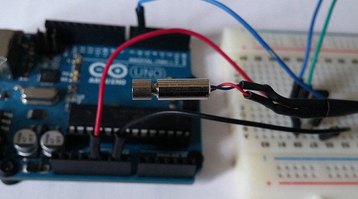
The Circuit
First, we need to connect the correct components. Thankfully, this is an extremely simple setup with some careful selection. There are 4 basic elements to our circuit, we’ll also offer some recommended additional components at the end.
For this we need:
- A microcontroller – in this case our Arduino (the actual processor is an ATmega328P)
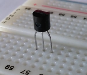
- A transistor – MOSFETs will suffice for applications that only use short vibrations and have small vibration motors, these can be either P-type or N-type
- A vibration motor
- A power source
There are two requirements for our power source, first is must provide a voltage at least our motor’s Rated Voltage. The second is that it must provide sufficient current, you can see your motor’s Maximum Start Current in its datasheet.
You can either chose to use an external power source, like a battery pack, or the Arduino’s built-in regulator. You can see that there are two output voltage pins, one at 3.3V and one at 5V. However, the 3.3V pin has a maximum current draw of 50 mA which isn’t enough for DC vibration motors. Instead, the 5V pin can supply ~450 mA which is more than enough for the majority of our vibration motors.
Using this 5V supply does, unfortunately, introduce another issue – as most of our motors have rated voltages of 3V or under we need some way of reducing the 5V supply. We’ve covered different options in a previous article, but with the Arduino, we’re in a perfect position to take advantage of its PWM function. This means we can take care of this in software and can keep our circuit nice and simple.
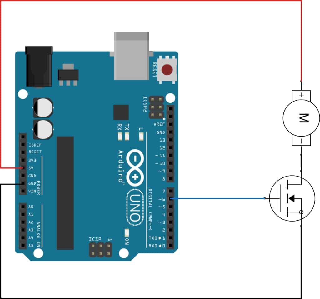
We’ve chosen to use an N-type MOSFET, the 2N7000, which affects how we connect our motor (which should be on the drain pin). We outline the process in greater detail in Application Bulletin 1: Discrete Driver Circuits for Vibration Motors, which discusses the use of both N-type and P-type transistors. Below is our basic N-type circuit.
Note that the gate of the MOSFET is connected to pin 6 of the Arduino. You can use another if you wish, but make sure that the pin is PWM enabled (denoted by a ‘~’ on the PCB).
The Code
Our transistor effectively acts as a switch, turning the motor on and off. It is important to note that with an N-type transistor it is “switched on” when there is a voltage above the transistor’s threshold voltage applied to the gate. Without going into too much detail, we are essentially turning the motor on when we set pin 6 to high and turning it off when set to low. Please note that for a P-type transistor this is the opposite.
Arduino has a basic-built in function for setting an output pin to high,digitalWrite(); however, with our current circuit setup, this will connect our 3V vibration motor to a 5V supply. Instead, we will use PWM to reduce the applied voltage.
Arduino’s PWM capability is actually hidden behind the analogWrite(); function. It takes arguments for the pin you are controlling and a value of 0 to 255 which determines the duty cycle – where 0 is 0% and 255 is 100% or ‘always on’. If you need background information on PWM and duty cycles you can read more in Application Bulletin 012: Driving Vibration Motors with Pulse Width Modulation.
In this example, we have a 3V motor and a 5V supply. This means we need to set the duty cycle to 3/5 = 60%. If 255 is 100%, then 60% is 153 ( = 255 * 0.6). So we can drive our motor at its rated voltage using the following command:
analogWrite( 6 , 153 );
And then to turn it off, we can use:
analogWrite( 6 , 0 );
Pretty simple!
We’ve added some delays (note the number is in milliseconds) to make the effect last longer, and we also set pin 6 to an output pin in the initial setup. Note that the main loop will continue as long as power is supplied, so once you run this program the only way to stop the motor vibrating is to cut the power!
The Next Steps
Responding to Inputs
Whilst the code above works, it’s nowhere near a complete product!
Typically, vibrations are only played when certain conditions are met. It might be a function of time, such as vibrating every 5 minutes, but in the vast majority of applications, it is a variety of different inputs that trigger a vibration effect.
We have lots of examples for basic applications with our Haptic Feedback Evaluation Kit, such as a Rugged Passcode System or a Wireless Temperature Warning System – you can access more in this link. These projects demonstrate how to build conditional states using if statements and switch/case statements, before coding you need to think about exactly when you want to play an effect.
Creating Effects
So far, the vibration motor simply turns on then off – not very exciting! Varying the vibration strength throughout the effect lets us create more advanced effects and vibration patterns like ‘ramps’ or pulses.
To change the vibration strength you simply need to call a new analogWrite(); function with a new value. So how might we go about creating a simple ramp-up effect? Well, there are two easy ways.
First, you can create the effect ‘on the fly’ (meaning we’ll calculate the values every time it is called). Try pasting the simple for loop into the sketch, replacing lines 6 to 12.
int x;for( x = 0 ; x < 154 ; x++ ) {
analogWrite( 6 , x );
}
analogWrite( 6 , 0 );
delay(3000);
This simple for loop will write the value of x as the duty cycle, starting at 0 and increasing by 1 each time the loop runs, up until the maximum value of 153. So we are increasing the power of the motor over time, creating a ramped input to the vibration motor. You may find that this ‘ramp’ is actually a bit quick – to extend the time you could add another short delay function inside the for loop to lengthen the time overall.
A second option is to store the waveform in an array and simply read the appropriate value from memory. Let’s say you had stored the numbers from 0 to 153 in an array called ‘ramp’, we would use two variables – one to store our position in the array and another to store the value from our position. We can change our for loop:
for ( x = 0 ; x < 154 ; x++ ) {y = ramp[x];
analogWrite( 6 , y );
}
It may not be immediately obvious why we might want to include this extra line of code, initially, it just appears more complicated. However, it is the basis for using much more advanced effects. For example, your array could contain the values that help build a half sine wave or sawtooth waveform.
Additional Components
We recommend some extra components to help stabilise the circuit.
Below is a circuit diagram that includes a Schottky diode and capacitor placed in parallel across the motor terminals (the capacitor should be as close to the terminals as possible) which will help with EMI suppression. Also, a pull-down resistor of 50kΩ ~ 100kΩ will help reduce quiescent current and keep the system stable.

You may also want to think about using more advanced motor drivers or even a haptic feedback chip. These have the benefit of offloading the work of playing an effect to another chip, allowing the microcontroller to focus on processing other tasks.
Finally, remember that mounting and connecting a vibration motor to an Arduino can be done relatively easy for a one-off prototype. However, it can quickly become impractical. At Precision Microdrives we offer vibration motors with connectors and different types of power leads. You can always contact our engineers to see what your best options are.
Newsletter
Sign up to receive new blogs, case studies and resources – directly to your inbox.

Sign up
Discover more
Resources and guides
Discover our product application notes, design guides, news and case studies.
Case studies
Explore our collection of case studies, examples of our products in a range of applications.
Precision Microdrives
Whether you need a motor component, or a fully validated and tested complex mechanism – we’re here to help. Find out more about our company.