AB-001
Discrete Driver Circuits For Vibration Motors
Overview
This bulletin covers the circuitry required to drive vibration motors from a high impedance signal source (for example an output pin of a microcontroller / digital device).
There are several integrated IC’s that can do this job, but if there is already a power supply of appropriate voltage in the application design, it is often cheaper to use discrete components.
Circuits like this are common in handheld applications where one may want to alert users and operators of an event. This is generally known as vibration feedback. For haptic feedback which is used more commonly with things like touch-screen interfaces, a more advanced drive circuit is usually employed.

Get in touch
Speak to a member of our team.
Motor catalogue
Looking for our products?
Reliable, cost-effective miniature mechanisms and motors that meet your application demands.
The Discrete Components Of Vibration Motor Drive Circuits
The output signals from digital microchips and microprocessor ports are designed to drive no more than 5~15mA. Since all vibration motors consume more current than this, a driver circuit is required to control the flow of power to these motors.
The most popular method to drive small vibration motors is to use a cheap enhancement-type (the most commonly available type) MOSFET. They are efficient and robust and the high-side configuration (P-type MOSFETs) can work well down to 1.5V supply voltages (N-channel MOSFETs work better from 2v or higher because they tend to have a higher Vgs gate turn-on-voltage).
Assuming that we are driving the vibrator motor with a digital / step signal, we use the MOSFET as a transistor switch – i.e. in its saturation region. Most small power MOSFETs can offer 95%+ efficiencies when switching, assuming they have a sub 0.25 Ohm Rds’s (this can be confirmed by looking at the MOSFET datasheet).
BJT transistors can also be used to drive a motor, but they are less efficient and require heat-sinking when high currents pass through them. Heat-sinking would also be required if one were to use a MOSFET in its linear region as well, but due to the high inefficiencies, it is unlikely that any applications would use this approach.
It goes without saying, that If you need to vary the speed of the motor, use a digital PWM and drive the MOSFET in its saturated mode of operation!
MOSFET designs come in two flavours for enhancement type devices:
- High-side – i.e. a P-channel MOSFET is used and the drive signal is active-low. This is required for 1.5V power supplies because N-channel MOSFETs tend to have a prohibitively high threshold voltage (Vgs).
- Low-side – i.e. an N-channel MOSFET is used, and the drive signal is active-high. N-channel MOSFETs generally have a lower on-resistance and therefore where there is enough drive voltage to be sure of putting the MOSFET in the saturated region it will be more efficient. Plus, N-channels are generally cheaper!
There are also some other components that often find their way into these designs. More specifically:
- An EMI suppression capacitor is sometimes used to reduce the high frequency electromagnetic wideband noise generated by the motor. A 10 to 100pF ceramic capacitor is generally suitable. It’s small enough not to interfere with the switching signal (e.g. with high-frequency PWM) but large enough to limit the larger voltage spikes from the motor caused by sparks in the commutator. Consider it optional; EMI from small vibration motors tends to be very low. Super-sensitive radio designs (e.g. in mobile phones) more deal with EMI more commonly via the use of series inductors.
- A ‘flyback’ diode to protect the MOSFET against voltage spikes from the coils. Because the inductance of small vibration motors is low, and because they’re driven by a low voltage, this can often be omitted when using motors from the Pico Vibe range of vibration motors.
- A pull up / down resistor. This is required to keep the MOSFET fully off when the active signal is not present. Since MOSFETs are charge controlled devices, without this resistor a gradual charge can build up on the gate and cause sporadic operation of the motor.
- A gate resistor. This can sometimes be useful to limit switching current from a very impedance source. With today’s logic and microcontroller products offering 5~15mA of supply drive, we’ve never seen the need to use one in this application.
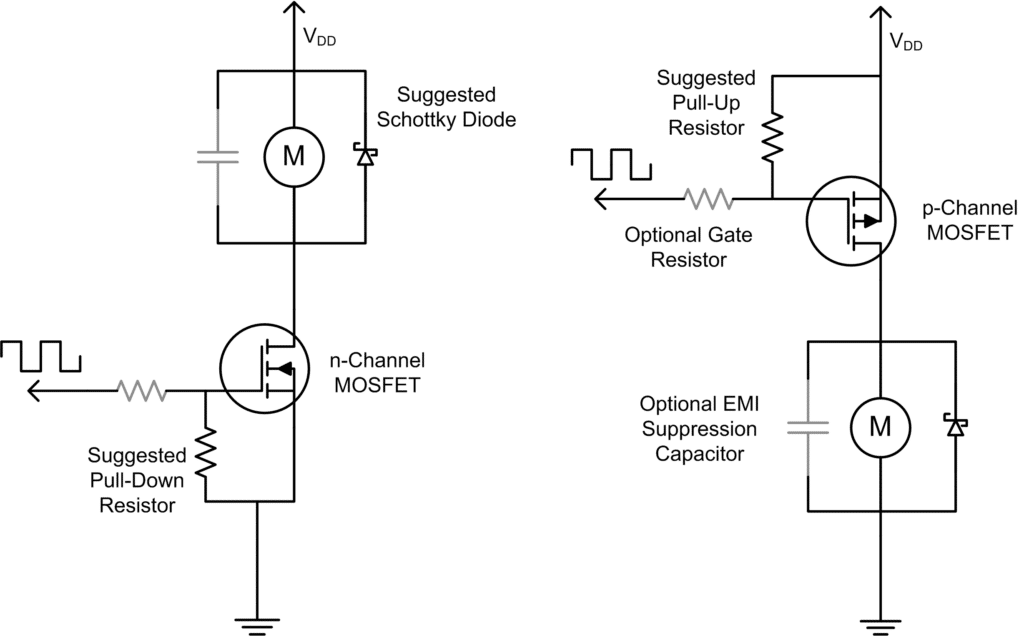
Reference Design Circuit Diagrams
The schematics below show two circuit configurations for a discrete MOSFET drive circuit for vibration motors. One is based on a low-side (left) with an N-channel MOSFET, whilst the other is based on a high-side (right) with a P-channel MOSFET.
Choosing Appropriate Components
We conclude this bulletin with some suggested component values for the above circuit reference designs.
The MOSFETs
The two standard MOSFETs that we use in our designs are the MGSF1N02LT1G (N-Channel) and the NTR4101PT1G (P-Channel) by On-Semiconductor.
We use both of these a lot in our own production projects. They offer a good balance between price (they’re cheap – typically USD $0.10 in 3k reels), low Vgs thresholds (typically 0.75v) and low Rds (typically 0.1 Ohm) values.
The EMI Capacitor
10pF to 100pF ceramic is generally considered optimum for use with PWM. If noise is an issue and you’re not using PWM, consider a larger, e.g. 100nF cap. If you need really good suppression, consider an X2Y suppression capacitor.
The closer you can place the capacitor to the motor terminals, the better it will work. Sometimes, through-hole or SMD PCB mounted vibration motors are chosen to keep lead lengths as short as possible.
The Schottky Flyback Diode
A diode that we used frequently, is also an On-semi part, MBR120ESF, though, like the MOSFETs, there are plenty of others available that would be suitable.
The Resistors
Nothing special here. To reduce quiescent current use 50k or 100k for the pull-up / down resistors. The gate resistor would be application specific and in some instances may be omitted.
Conclusion
This application bulletin presented a couple of best practice methods for driving vibration motors with discrete MOSFETs. Remember to take a look at other application bulletins which may cover different aspects of this subject. You can always find these on our vibration motors application note page.
Newsletter
Sign up to receive new blogs, case studies and resources – directly to your inbox.

Sign up
Discover more
Resources and guides
Discover our product application notes, design guides, news and case studies.
Case studies
Explore our collection of case studies, examples of our products in a range of applications.
Precision Microdrives
Whether you need a motor component, or a fully validated and tested complex mechanism – we’re here to help. Find out more about our company.