Haptic Feedback Evaluation Kit Tutorial: Vibration Alerts on an External Actuator
Looking for our Haptics range? View our main Haptics hub here.
Using Vibration Alerts With External Actuator
Note: This article discusses using the MOSFET to play vibration alerts on an external actuator. Therefore, it’s only applicable to ERMs and not LRAs (which require an AC signal).
The Haptic Shield has two SMD test points for connecting an external actuator, OUT+ and OUT-. To aid development on the DRV2605, these are designed to be as true a connection to the output pins as possible. Unfortunately, this design choice means the test points are not connected to the MOSFET and vibration alerts (which are played using a PWM signal and the transistor) are not available on external actuators.
There are two possible solutions that enable the use of the Haptic Feedback Evaluation Kit’s vibration alerting functions. By implementing either of these options, you will be able to use the Vibration Alerting Tutorial in Intro Mode, Vibration Alerting waveform builder in Engineering Mode, or the functionplayVibAlert(); in Development Mode.
Method 1: Stripped Ribbon Cable (Easiest)
This is not the recommended method because it prevents using the Haptic Grip without reassembly, but it is the simplest and quickest way to access the output from the MOSFET.

By cutting the connector from the Haptic Grip end of the grey ribbon cable it is possible to gain access to the drive signal intended for the actuators in the grip. The ribbon cable has 6 leads:
| Pin | Signal | Note |
| 1 (Red) | Drive Signal | MOT+ |
| 2 | Drive Signal | MOT- |
| 3 | Actuator Select | SIG_1 |
| 4 | Power | GND |
| 5 | Power | VCC (+5 V) |
| 6 | Actuator Select | SIG_2 |
By stripping leads 1 and 2, you can connect these to your own actuator. The method below is preferred because it is not permanent and does not involve directly modifying the kit.
Method 2: External MOSFET Circuit (Recommended)
Before progressing with this method, please disconnect the Haptic Grip from the Haptic Shield.
You can access the Haptic Shield’s schematics here. The MOSFET circuit is extremely simple (located middle right) and can be easily replicated on a breadboard. In fact, if you intend to develop something using vibration alerting it is likely you may already have various transistors for prototyping.
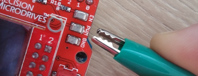
In addition, the PWM signal from the Arduino has its own SMD test point for external access. In normal operation this can be used to analyse the PWM signal through an oscilloscope, however here we will use it as an input to the external MOSFET circuit.
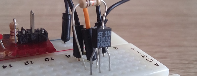
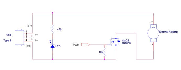
On a breadboard, connect the following circuit:

This replicates the design on the Haptic Shield and Haptic Grip, except there are no losses due to switches (which are used to direct the drive signal to the chosen actuator). The NMOS used in the Haptic Feedback Evaluation Kit is the BSS138PW, however, the image below uses a 2N7000 NMOS (in a more manageable TO-92 package).
The PWM signal is taken directly from the SMD test point on the Haptic Shield:
Note that all modes of operation are intended to use an NMOS design, and although it is possible to use P-type transistors, this is the preferred circuit.
The final step is to find a 5 V source to connect to the external actuator.
Accessing 5 V Sources
Many users will have an external power supply that will offer 5 V, which is the best option because you can simulate your final design with greater accuracy.
The Arduino Uno can only negotiate 500 mA from the USB source – which it must use to power the motor in addition to the processor, capacitive touch driver, OLED screen, etc. As some of these will not be included your the final design, their current consumption is redundant. A better approach is to figure out how much current will be available to your motor and limit your power supply accordingly.
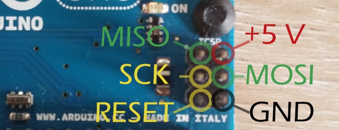
Alternatively, the Arduino Uno has a collection of 6 headers at the top of its board (opposite end from the USB port) marked ICSP. Two of these pins offer a 5 V connection and a ground connection, which can be accessed with jumpers:
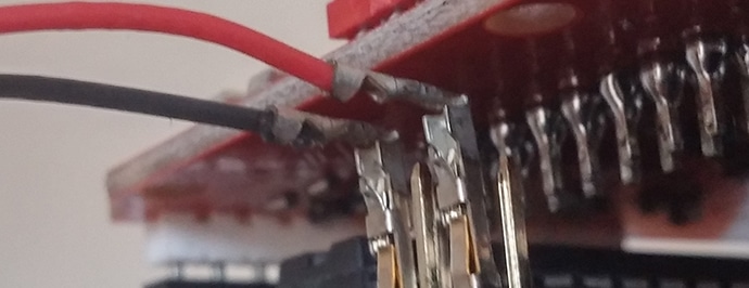
However, in order to fit the Haptic Shield on too, the jumpers must be bent:
A third option is to make use of a USB cable. Below is a simple circuit that includes a USB connector and a set of jumpers that connect to the breadboard:
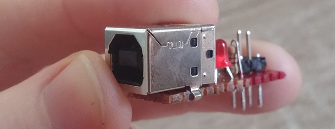
This supplies a steady 5 V to the breadboard but is limited to 100 mA when connected to a computer. For more current, simply connect the USB cable to a wall charger. This is surprisingly useful for quick tests if you don’t have a regulated power supply! If you’re interested in building the circuit, the schematic is below. The LED is a simple power light to show when the unit is properly connected to the USB supply.
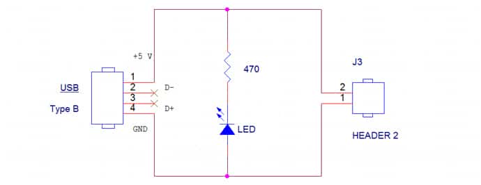
Pins 2 and 3 are the data lines, which can be left as an open circuit. Note that if using a stripboard and a USB socket like the image above, double-check none of the pins are accidentally connected to each other. Micro and Mini USB ports can also be used, although these have 5 pins where pin 1 is still +5 V, pin 5 is GND.
You could also combine this with the MOSFET circuitry to make a complete development board. This enables you to accept a PWM signal from any source and power your motor from a USB cable supplying 5 V with a few inexpensive discrete components:
5 V Supply, Rated Voltage, And Duty Cycles
Finally, a special note regarding the PWM duty cycle and the applied voltages. This has been written assuming an NMOS transistor is used – for a p-type circuit you need to invert the duty cycle values (e.g. to power a motor at 1/4 speed you must use a 75% duty cycle instead of the normal 25%).
For a full guide on PWM with vibration, motors see our Application Bulletin here. The rough idea is that the voltage applied to the motor is the supply voltage multiplied by the duty cycle. For example, a 5 V supply with a 50% duty cycle results in an equivalent voltage of 2.5 V (75% would equal 3.75 V and 25% would equal 1.25 V).
If your external actuator is rated at 3 V you must be careful not to set the duty cycle above 60% (unless you are deliberately using overdrive for a short pulse). However, if you are making use of the Haptic Feedback Evaluation Kit’s PWM signal then this has already been scaled to the correct level for the selected actuator.
As an example, we can consider building a vibration alert waveform and playing it through the 306-109 located in the Haptic Grip. The kit knows this motor is rated at 3 V, so if you set the ‘Power’ variable to 100% the kit actually uses a PWM duty cycle of 60%.
Therefore, when connecting your own external actuator with Engineering Mode the actuator selection is still important as it sets the maximum output voltage. The table below shows the rated voltage of the included actuators, either select one that has the same rated voltage or reduces the Power variable accordingly.
If building your own PWM function, you should manually scale your duty cycles. The easiest way of accomplishing this is to calculate the ratio between the motor’s rated voltage and the 5 V maximum. For example, for a motor rated at 2.7 V:
ScalingRatio=2.75=0.54ScalingRatio=2.75=0.54
The Arduino’s functionanalogWrite(); is not a true analogue signal, it is actually a PWM waveform. It accepts two arguments, the first is the output pin and second is the duty cycle value. The duty cycle is an integer value between 0 (always off, 0%) and 255 (always on 100%). Below is a table that shows the duty cycle and equivalent value foranalogWrite();.
| Model Number | Rated Voltage | Typical Normalised Amplitude | Duty Cycle @ 100% Power | Equivalent analogWrite();Int Value |
| 305-000 | 1.3 V | 0.8 G | 1.3 / 5 = 26% | 255 x 26% = 66 |
| 306-109 | 3 V | 3.5 G | 3 / 5 = 60% | 255 x 60% = 153 |
| 308-102 | 4.5 V | 5.5 G | 4.5 / 5 = 90% | 255 x 90% = 230 |
| Example | 2.7 V | ??? G | 2.7 / 5 = 54% | 255 x 54% = 138 |

Get in touch
Speak to a member of our team.
Motor catalogue
Looking for our products?
Reliable, cost-effective miniature mechanisms and motors that meet your application demands.
Newsletter
Sign up to receive new blogs, case studies and resources – directly to your inbox.

Sign up
Discover more
Resources and guides
Discover our product application notes, design guides, news and case studies.
Case studies
Explore our collection of case studies, examples of our products in a range of applications.
Precision Microdrives
Whether you need a motor component, or a fully validated and tested complex mechanism – we’re here to help. Find out more about our company.