Quick LRA Debugging
Introduction
Linear resonant actuators are more difficult than their DC motor-based ERM counterparts. They should be driven with an AC signal at their resonant frequency, which is one of the reasons we recommend using a dedicated driver.
However, adding in drivers can quickly make a system quite complicated – especially if using I2C to communicate. This introduces difficulties when trying to debug if the LRA isn’t vibrating how do you know where the error is? Is the microcontroller code, the driver circuit, or a problem with the LRA itself?
You may be wondering why we recommend drives if they’re more complicated to use, simply put they have many useful features (such as auto-resonance detection, overdriving, etc) that make the complexity worthwhile. It’s also worth noting that the complications encountered during prototyping are unlikely to be an issue when in production. If you’re interested in using a driver you should certainly read our Application Bulletin on driving LRAs.
Concept
If you weren’t concerned with driving the LRA properly (and just wanted to test if it was faulty) you might consider sending a PWM signal, but the LRA still needs the signal to be at the resonant frequency. PWM frequencies are often in the high kilohertz range and are difficult to get down to ~175 Hz.
Solution
Mechanically, LRAs are quite similar to speakers, a voice coil creates the oscillating movement of a mechanical component. So here we’re proposing a fairly simple alternative, treating the LRA like a simple speaker and playing an audio file (of the correct frequency) through it. This technique can also be used if you are unsure of an LRAs resonant frequency.
Hardware
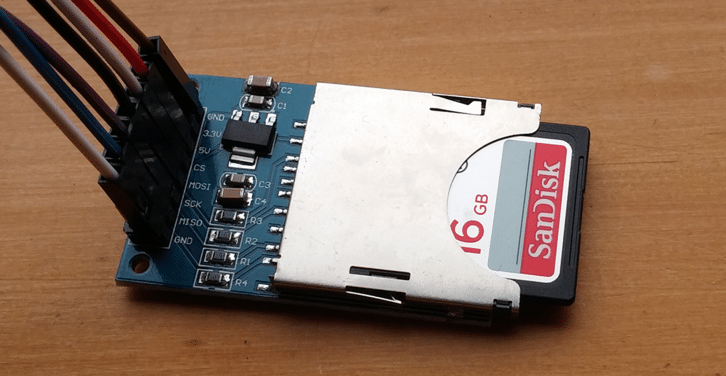
This can be easily set up with a few modules. First, we’re using the same Arduino Uno R3 that’s used in our Haptic Feedback Evaluation Kit. We also need a method for storing the audio file somewhere the Arduino can access it – we’ve chosen a simple SPI-based SD card module. These are extremely inexpensive, easily connected to the Arduino and readily sourced at DIY electronics stores or online. Also, a transistor (we’ve used a 2N7000 NMOS) is used to amplify the signal so it can be played through the LRA. Finally, a low-value resistor is used to limit the voltage drop across the LRA – as we’re simply testing that the LRA is operational we don’t need to be too picky about its value, just make sure it’s a couple of times the value of the LRAs terminal resistance (somewhere between 20 to 50 Ohms should work).
To summarise, we require the following components:
Arduino Uno
SD Card Module
Transistor (e.g. 2N7000)
Low-Value Resistor (e.g. we’ve used a 22 Ohm)
An LRA, we’re using the C10-100 (resonant frequency 175 Hz)
Why Use an Audio Signal?
The main benefit of using an audio file as the drive signal is that you can easily create/manipulate it using computer software, instead of using ‘for’ loops and arrays in the Arduino code. We’ve used Adobe Audition CC, but Audacity is a great free alternative.
Playing the audio file requires the excellent TMRpcm Arduino library, available here. This library is limited in the audio files it can play – so when generating your audio file ensure it has the following settings:
Sample Rate: 16000 Hz
Bit Depth: 8 Bit
Channels: Mono
Format: .wav
Generating the Audio Files
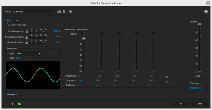
We’ve generated two audio files, one that’s a 175 Hz sine wave and another that sweeps between 140 – 210 Hz, both made using the Effects -> Generate -> Tone function in Adobe Audition. The first file simulates the basic operation of the LRA to test it is functional, and the second demonstrates how you can try to find the resonant frequency by sweeping across a set range of frequencies.
Set the Base Frequency to 175 Hz, enable one Frequency Component and set its multiplier to ‘1’ (or frequency to 175 Hz) for the single tone. Note the duration in the bottom left, we chose 5 seconds. To perform a sweep there’s a checkbox in the top left ‘Sweep Frequencies’. Here we set the Base Frequency to 140 Hz and in the End tab we set it to 210 Hz, this defines the range of frequencies that our tone will sweep across. Remember to match up the frequencies in the Frequency Components box so it matches the Base Frequency (always has a Multiplier of 1). We’ve provided a download zipped in the end.
Circuit
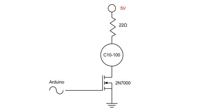
Once you’ve created the audio files, copy them onto an SD card (if you’re using the SD card module). We need to then connect the testing circuit before finally programming the Arduino. The circuit is pretty simple, the LRA is in series with the resistor and its negative terminal is connected to the drain of the NMOS. The source is connected to ground, and the gate goes to pin 9 of the Arduino (set by the TMRpcm library).
SPI SD Card Connection
Connecting the SD Card is dependent upon your selected module, but if it’s SPI based the connections below should work, if you’re using a different Arduino you can find connection details here, or refer to your microcontroller’s datasheet:
| Arduino Board | MOSI | MISO | SCK | SS / CS |
| Uno or Duemilanove | 11 or ICSP-4 | 12 or ICSP-1 | 13 or ICSP-3 | 10 |
| Mega1280 or Mega2560 | 51 or ICSP-4 | 50 or ICSP-1 | 52 or ICSP-3 | 53 |
Code
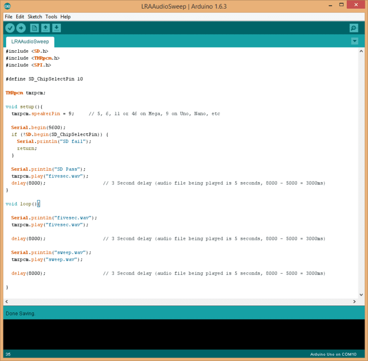
Finally, the code is made incredibly simple thanks to the libraries available. The SD card’s chip select pin (SS / CS in the table above) is defined on line 5 and the speaker pin (the connection to the transistor gate) is set on line 10.
Once initialised we can do the following (in order):
- check that we can connect to the SD card
- play the fivesec.wav audio file
- play the sweep.wav sweep file
- repeat playing the audio files
Files are played using the tmrpcm.play("filename"); command, where the file name must exactly match that of the audio file, i.e. fivesec.wav or sweep.wav. We’ve added a 3-second delay between each file, note that the length of the delay also needs to account for the length of the audio file because the code immediately continues through the program once the play command is sent – there’s no ‘completed’ confirmation. For example, in this case, we have two 5 second audio clips and desire 3 seconds between them, so our delay must wait for the file to finish and for the desired delay: 5s + 3s = 8s.
Testing the LRA
Assuming the frequency in your fivesec.wav matches the resonant frequency (or is very close to) of the LRA, you should feel the LRA vibrate at a steady amplitude. During the sweep.wav, you should feel the amplitude increase and fall away as it approaches, hits, then leaves the resonant frequency.
The sweep.wav file could easily be extended in length to sweep at a slower pace, or the range shortened, which would help find the rated resonant frequency of the LRA – it’s often 175 Hz or 205 Hz.
The maximum amplitude will be dependent upon the supply voltage (5V in our case) and the size of the series resistor. We recommend erring on the side of caution so your test doesn’t accidentally damage the LRA – we started with 50 Ohm before reducing it to 22 Ohm. The amplitude could only be felt when the LRA was held directly, but it proved the LRA was functional with minimal risk.
Download the Files
The files in the zip include:
- Sample Arduino sketch (written for the Uno R3)
- 5s audio file at 175 Hz (.wav format)
- 5s audio file, sweeping from 140 Hz to 210 Hz (.wav format)
If you need any further help debugging your LRA, you can always contact us for assistance!

Get in touch
Speak to a member of our team.
Motor catalogue
Looking for our products?
Reliable, cost-effective miniature mechanisms and motors that meet your application demands.
Newsletter
Sign up to receive new blogs, case studies and resources – directly to your inbox.

Sign up
Discover more
Resources and guides
Discover our product application notes, design guides, news and case studies.
Case studies
Explore our collection of case studies, examples of our products in a range of applications.
Precision Microdrives
Whether you need a motor component, or a fully validated and tested complex mechanism – we’re here to help. Find out more about our company.