AB-020
Understanding Linear Resonant Actuator Characteristics
Introduction
Linear Resonant Actuators (LRAs) are becoming more popular for haptic applications. They are an alternative to eccentric rotating mass vibration motors and have several distinct advantages. For example, they have better haptic performance characteristics and are more efficient (at resonance – see more about this below). For these reasons, they are used in many handheld and touchscreen devices, amongst other applications.
Unfortunately, there is little theory or application notes on these devices. This Application Bulletin describes the operation of the LRA, detailing how it creates vibrations, modelling it as a mechanical system, and provides an equivalent circuit.
We also cover some advanced features that LRA drivers use and explain how they are able to achieve these.
Theory Of Creating Vibrations With An LRA
As with Eccentric Rotating Mass vibration motors (ERMs), the vibrations created by an LRA are based upon the movement of a mass which causes repeated displacement.
Firstly, to remind readers, the ERM has an off-centre load, when it rotates the centripetal force causes the motor to move. The rotation is created by applying a current to the armature windings attached to the motor shaft. As these are inside a magnetic field created by the permanent magnets on the inside of the motor’s body, a force is created causing the shaft to rotate. To ensure the rotation continues in the same direction, the current in the windings is reversed. This is achieved by using static metal brushes at the motor terminals, which connect to a commutator that rotates with the shaft and windings. The different segments of the commutator connect to the brushes during rotation and the current is reversed, maintaining the direction of rotation.

Get in touch
Speak to a member of our team.
Motor catalogue
Looking for our products?
Reliable, cost-effective miniature mechanisms and motors that meet your application demands.
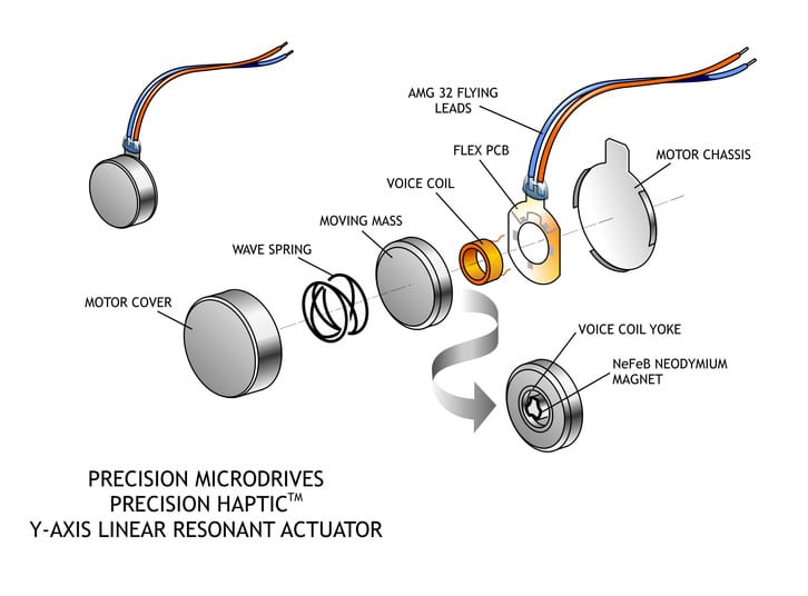
In a similar method, LRAs use magnetic fields and electrical currents to create a force. One major difference is the voice coil (the equivalent of the armature windings) remains stationary and the magnetic mass moves instead. The mass is also attached to a spring, which helps it return to the centre. Driving the magnetic mass up and down causes the displacement of the LRA and thereby the vibration force.
As the voice coil remains stationary and the direction of the force on the magnet must be switched, the direction of the current in the voice coil must also be switched. This means that LRAs require an AC drive signal to function correctly.
The LRA works in a similar way to how a loudspeaker creates music. In a loudspeaker, the speaker cone is used to produce audio waves through displacement. However, a loudspeaker is designed to operate over a range of frequencies, whereas an LRA is tuned to its resonant frequency as we see later.
Modelling As A Mechanical System
If you have read our previous Application Bulletin 004: Understanding ERM Vibration Motor Characteristics then you will be familiar with the One Degree of Freedom model. To recap, when analysing the behaviour of the eccentric rotating mass vibration motor we approximated the system to produce vibrations in one axis only, i.e. with one degree of freedom. The one DOF model is actually represented by a mass which is connected to a spring that moves up and down, sound familiar? It should, this exactly describes the LRA!
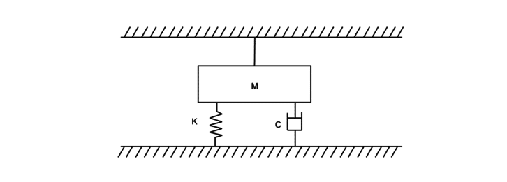
As the LRA fits the one DOF model perfectly, we can use the same equation of motion from AB-004 to describe the system. We consider the stiffness of the spring (k), the damping (c) (representing the losses of the system), and the motion of the magnetic mass (M).
The force from a single spring with the stiffness (k) is taken from Hooke’s law:𝐹=𝑘𝑥
The viscous damping is proportional to the velocity of the mass (represented below as the derivative of the displacement):𝐹=𝑐𝑓𝑟𝑎𝑐𝑑𝑥𝑑𝑡
Following Newton’s second law of motion, the magnetic mass’ motion is described as:𝐹=𝑀𝑓𝑟𝑎𝑐𝑑2𝑥𝑑𝑡2
The three forces above are equal to the input:𝐹0=𝐴𝑠𝑖𝑛(𝑜𝑚𝑒𝑔𝑎𝑡)
Therefore our full equation for the system is:(𝑀)𝑓𝑟𝑎𝑐𝑑2𝑥𝑑𝑡2+𝑐𝑓𝑟𝑎𝑐𝑑𝑥𝑑𝑡+𝑘𝑥=𝐹0𝑠𝑖𝑛(𝑜𝑚𝑒𝑔𝑎𝑡)
Equivalent Electrical Circuit And Resonant Frequency
We have shown above that the mechanical system of the LRA is very similar to that of a loudspeaker. As a result, the electrical equivalent is also much like a loudspeaker or voice coil motor.
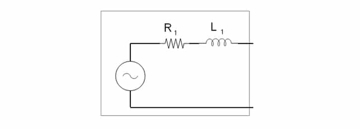
The LRA can be broken down into two sections of passive components. First, we have the impedance created by the voice coil and terminals. This is comprised of a resistor and inductor, similar to our equivalent model of the DC motor:
Secondly, we have a capacitor, resistor, and inductor in parallel. Together these represent the impedance of the mechanical section of the LRA as the magnetic mass moves from the current through the voice coil:
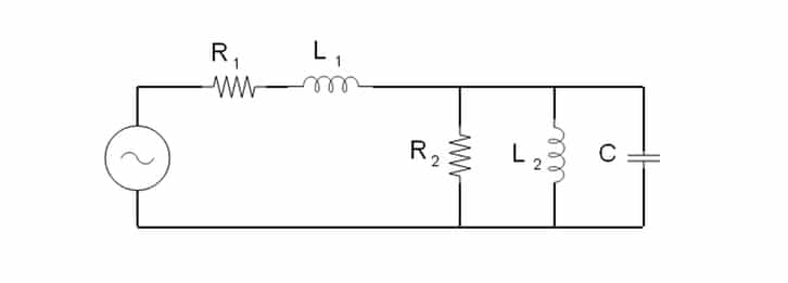
Together, the complete equivalent circuit looks like this:
The overall impedance of the parallel circuit is given as follows:𝑓𝑟𝑎𝑐1𝑍𝑡𝑜𝑡=𝑓𝑟𝑎𝑐1𝑍𝐶+𝑓𝑟𝑎𝑐1𝑍𝑅2+𝑓𝑟𝑎𝑐1𝑍𝐿2
Where:𝑍𝐶=𝑓𝑟𝑎𝑐1𝑗𝑜𝑚𝑒𝑔𝑎𝐶𝑍𝑅2=𝑅𝑍𝐿2=𝑗𝑜𝑚𝑒𝑔𝑎𝐿
While the impedance of the capacitor decreases with higher frequencies ( ( omega) is the frequency), the impedance of the inductor increases. This leads us to see that there is a specific frequency where the capacitor and inductor impedances balance to leave the mechanical sections’ impedance is at its maximum. With the mechanical section’s impedance maximised, there is a greater voltage drop and therefore the mass moves with greater force. This specific frequency is known as the resonant frequency.
Resonant Frequency
When LRAs are driven with a frequency other than their resonant frequency, the performance and efficiency is dramatically reduced. As the capacitor, resistor, and inductor are equivalent components that represent the mechanical properties of the LRA, the values of these components can change over time or depend on environmental characteristics. For example, as the LRA ages, the spring may lose its elasticity, or the material the LRA is mounted to may affect how the casing moves under the vibration force. This manifests itself as variations in the resonant frequency which we explain how to overcome electronically in the next section.
This leads to an interesting feature of the LRA. With ERMs the input voltage affects the speed of the motor, which in turn affects both the vibration amplitude and the vibration frequency. For LRAs the voltage and frequency are separated. Although we cannot adjust the vibration frequency, the vibration amplitude can be varied without impacting the vibration frequency. This is an attractive feature for those who wish to keep their vibration frequency in a specific range but still produce haptic waveforms.
The LRA As A Circuit Component
When LRAs are included in a circuit they are often simplified beyond their equivalent circuit. One reason for this is that they are usually driven by a dedicated LRA driver chip such as DRV2603. When using a stand-alone IC, the LRA can simply be connected to the appropriate pins. This allows designers and engineers to save time and concentrate on other sections of the system.
Although the LRA does produce back EMF, and in other Application Bulletins we have taken steps to reduce the impact of this effect, many LRA drivers actually use the back EMF as a sensing mechanism. In the Equivalent Circuit section above, we discussed how the resonant frequency of the LRA will shift. Certain driver ICs measure the back EMF and use this information to adjust the frequency of the drive signal to find the resonance. This allows the product to perform within closer limits and levels regardless of conditions or age.
It’s worth noting that LRA’s are effectively brushless and don’t suffer from the electromagnetic emissions that come from commutator arcing in DC ERM motors. This means that like brushless ERM motors, LRA’s are generally suitable for ATEX certified equipment.
Basic And Advanced Control
The simplest way to drive the LRA is using a bench-top signal generator and amplifier. This is how most users perform initial testing when evaluating devices. However as most LRAs are used in haptic applications, drivers need to be portable or compact – unlike lab-based signal generators.

Creating an AC signal in digital electronics requires a DAC or advanced PWM signals coupled with high-order filters. Before LRAs became popular, the most common source of AC signals were audio processors used for headphone or speaker outputs. Whilst these can be used to drive LRAs (assuming they offer sufficient output current), there are now dedicated chips for driving LRAs. These will accept simplified PWM signals to control the vibration strength and create the appropriate AC signal.
They also enable more advanced haptic performance through a variety of features.
The haptic characteristics of LRAs are much better than their ERM counterparts, with the exception of Typical Stop Time. Our C10-100 has a Typical Start Time of 5ms, which is below all ERM motors by some margin.
However, springs are very good at storing energy, so the magnet takes a long time to come to rest. Our testing has shown the Typical Stop Time to be 275ms (C10-100). To improve the ‘crisp’ haptic effect this needs to be reduced, achieved by a technique called reverse braking. ERMs do this by reversing the polarity of the DC voltage. Reverse breaking with LRAs works in a similar way by shifting the phase of the AC signal by 180°, which essentially reverses the polarity. This creates an electromagnetic force on the mass in the opposite direction to its velocity, thus stopping it quicker. Practically this is only achievable using dedicated LRA driver ICs.
For more information on LRA, drivers see Application Bulletin 003: Driving Linear Resonant Actuators.
Conclusion
We have demonstrated how LRAs produce vibrations by explaining their electrical and mechanical operation. This included an overview of their internal construction and comparing it to its ERM counterpart and highlighting its similarity to a loudspeaker.
We further described the system by deriving an equation of motion based upon the one degree of freedom model. An equivalent circuit was also produced, taking into consideration both the electrical and mechanical sections of the system and representing them as passive electrical components.
From the equivalent circuit, we were able to explain the presence of a resonant frequency, this is the only frequency at which the LRA will vibrate. As this resonant frequency can shift depending on a variety of factors, it proposes a problem for designers.
The shifting resonance problem, as well as other driving complexities, can be solved using a dedicated LRA driver IC of which there are several covered in our AB-003. Other advantages of using a driver IC were highlighted by explaining the operation of advanced features, such as active braking.
Newsletter
Sign up to receive new blogs, case studies and resources – directly to your inbox.

Sign up
Discover more
Resources and guides
Discover our product application notes, design guides, news and case studies.
Case Studies
Explore our collection of case studies, examples of our products in a range of applications.
Precision Microdrives
Whether you need a motor component, or a fully validated and tested complex mechanism – we’re here to help. Find out more about our company.