Are DC motors reversible?
Simply put, DC motors can turn in either direction (clockwise or counter-clockwise) and can be easily controlled by inverting the polarity of the applied voltage.
Strictly speaking, the motors can actually create a force in either direction. We make this important distinction because some applications, such as haptic feedback, make use of ‘braking’ to control the motor without it actually turning in the opposite direction. If a motor is already in motion, the applied voltage can be inverted and the motor will decelerate quickly, eventually stopping. If the voltage continues to be applied, the motor will start again rotating according to the voltage polarity.
Fleming’s Left-Hand Rule and DC Motors
The direction of force, and therefore rotation, is explained using Fleming’s Left-Hand Rule for Motors.
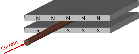
First, we will use a (very) simplified model of a motor – imagine two magnets of opposite poles (N and S) separated by a small air gap, with a wire in between which carries an electrical current. This is essentially how a motor is constructed, although in this simplified example we imagine single-pole magnets of infinite length to avoid introducing the complications like the commutator. This concept holds perfectly well for explaining the important part of the theory.

Get in touch
Speak to a member of our team.
Motor catalogue
Looking for our products?
Reliable, cost-effective miniature mechanisms and motors that meet your application demands.
When the wire is allowed to move freely and carries current through the magnetic field, a force acts upon the wire causing it to move. In a motor, the coils can be attached to the rotor so when the force acts upon the wire it causes a rotation of the shaft. In our simplified diagram, we can say that the wire moving to the left is the equivalent of the motor turning counter-clockwise, and moving right is clockwise.
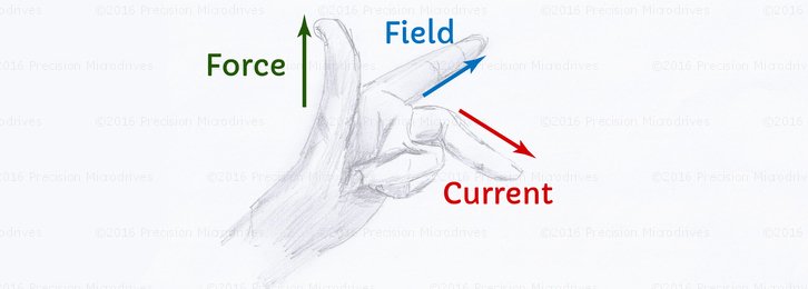
Now, we apply Fleming’s left-hand rule to determine the direction of the force. The resulting force is perpendicular to both the magnetic field and the direction of the current. Using the hand position in the image at the top of the article, you can position your left hand to replicate the image below. You may want to wait until you are alone in the office because you will look quite strange!
- Your first finger represents the magnetic field, pointing straight down to the floor.
- Your middle finger represents the current, pointing towards the computer screen.
- Your thumb represents the resulting force, which points left.
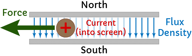
This shows us that with the current flowing through the wire “into” the computer screen will cause a force pushing left, in our model, this is equivalent to the motor turning counter-clockwise.
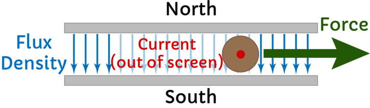
Now, the bit we are most concerned with is how we change the force so the wire travels in the opposite direction, causing our motor to rotate in ‘reverse’. We can use Fleming’s left-hand rule again, with the same magnetic field, but this time use our thumbs to point right instead of left. As a result, your middle finger should now point towards yourself, showing the current flows out of the screen.
This shows that in order to make the motor rotate clockwise, we must reverse the flow of current (i.e. changing the flow of current changes the direction of the force by 180 degrees).
Of course, the direction of current is controlled by the polarity of the voltage. So in order to change the direction of rotation, we can simply reverse the voltage, causing the current to flow in the opposite direction, changing the force by 180 degrees and the motor to be driven ‘backwards’.
Practical Implications – How to Reverse the Voltage
If you are unfamiliar with electronics, changing the polarity of the voltage may sound more difficult than it really is. In fact, you are more likely to struggle with the control logic – that is deciding and commanding when to reverse the polarity. You can easily drive the motor in either direction with a single chip, however, this does depend on your application.
Let’s take two example applications that drive a motor in either direction, a locking mechanism and a haptic feedback device.
The locking mechanism uses a gearmotor, which is driven in either direction to lock or unlock a door. When a motor needs to actually rotate both clockwise and counter-clockwise, one of the most popular driving chips is called an H-bridge. These are discrete components that house 4 transistors acting as switches, one pair of switches is used to drive the motor one way whilst the other two are used for the reverse direction. The control for the motor direction (often simple GPIO signals) is separate to the drive voltage which controls the speed, so you can vary them independently of one another.
Conversely, haptic feedback devices implement ‘active braking’ which is used to stop the motor quicker and improve the crispness of effects. Here, the motor does not actually rotate in the opposite direction at any point, instead, we use the effects of a reverse voltage to control the motor with greater precision. Many haptic chips implement active braking by default, either as a setting in the chip or as part of a pre-programmed waveform – which makes it very easy to implement.
Discover more
Resources and guides
Discover our product application notes, design guides, news and case studies.
Case studies
Explore our collection of case studies, examples of our products in a range of applications.
Precision Microdrives
Whether you need a motor component, or a fully validated and tested complex mechanism – we’re here to help. Find out more about our company.