AB-002
Discrete H-Bridge For Enhanced Vibration Control
Overview
This bulletin covers some more advanced circuitry that is useful if we need better control of the vibration motors we’re using. A prime application for this, is, of course, using a vibration motor to provide haptic feedback.
When using vibration motors (or Eccentric Rotating Mass (ERM) actuators to give them their popular engineering term) for haptic feedback applications, the ability to generate crisp clean ‘impulse’ signals is very important. Factors like the eccentric mass size and shape can affect this, which is why all our vibration motor datasheets have Rise, Lag, Stop and Active Brake times listed.
A popular technique to reduce the time taken for the vibration motor to start spinning is to overdrive the voltage applied to the motor for a short period of time. However, it’s the stop time that has the biggest effect on the production of a crisp haptic event.
In order to improve the stop time, we have to drive the motor hard with reverse polarity (active braking) in order to create a ‘brake’ for the momentum of the eccentric mass. To apply this reverse voltage, we need to use an H-bridge drive circuit.

Get in touch
Speak to a member of our team.
Motor catalogue
Looking for our products?
Reliable, cost-effective miniature mechanisms and motors that meet your application demands.
The H-Bridge Drive Circuit Reference Design
The H-bridge design builds on the basic driving circuitry covered in AB-001 (simple driver circuits for vibration motors). A reference circuit diagram can be found below.
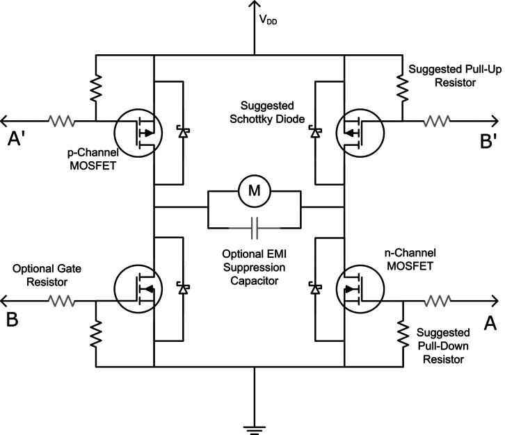
The H-bridge is a more complex drive configuration that makes use of four transistors; two pMOS for the high-side of the circuit and two nMOS for the low-side. These can be in the form of a single package that contains all the transistors and diodes, or if board-space is available, it can often be made cheaper with discrete components.
Normal brushed motors (like vibration motors) can be operated in ‘four quadrants’, in other words, they have four modes of operation: forward drive, reverse braking, reverse drive and forward braking. In the case of haptic feedback, we’re going to ignore the ‘braking’ quadrants, and drive the motor either in forward drive to initiate vibration, or when we want to stop the vibration quickly (at the end of the haptic event), reverse drive the motor long enough to make it stop.
Driving Signals: Forward Drive And Reverse Drive Pairs
The actual direction that the motor goes will depend on its polarity connection in the middle. But for this example, let us consider that ‘forward’ drive occurs when signal A is set high, and reverse drive occurs when signal B is high.
Note that for the H-bridge to work we will also need A’ and B’ which are the A and B drive signals NOTted, i.e. when A is high, A’ has to be low.
If we’re using an MCU with two built-in PWM drivers, for example, one for A signals and B signals (e.g. an Atmel AT90PWM316), we can generate A’ and B’ signals with a logic NOT gate, or a single nMOS inverter.
Driving Signals: Dead-Gap
When driving the H-bridge it is important to note that because PMOS and NMOS transistors turn on and off at different speeds, it is possible to create transient short-circuits along the two vertical paths of the H-bridge which can destroy the transistors.
The solution to this is to have a dead-gap – I.e. a period where there are no drive signals when transitioning between forward drive and reverse drive. This will ensure that all the transistors in the bridge are in an off-state before turning the next pair of transistors on.
Many MCU’s (e.g. Atmel) have dead-gap circuits as part of their PWM signal generator hardware.
Choosing Appropriate Components
We conclude this bulletin with some suggested component values for the above circuit reference designs.
The MOSFETs
The two standard MOSFETs that we use in our designs are the MGSF1N02LT1G (N-Channel) and the NTR4101PT1G (P-Channel) by On-Semiconductor.
We use both of these a lot in our own production projects. They offer a good balance between price (they’re cheap – typically USD $0.10 in 3k reels), low Vgs thresholds (typically 0.75v) and low Rds (typically 0.1 Ohm) values.
The EMI Capacitor
10pF to 100pF ceramic is generally considered optimum for use with PWM. If noise is an issue and you’re not using PWM, consider a larger, e.g. 100nF cap. If you need really good suppression, consider an X2Y suppression capacitor.
The closer you can place the capacitor to the motor terminals, the better it will work. Sometimes, through-hole or SMD PCB mounted vibration motors are chosen to keep lead lengths as short as possible.
The Schottky Flyback Diode
A diode that we used frequently, is also an On-semi part, MBR120ESF, though, like the MOSFETs, there are plenty of others available that would be suitable.
The Resistors
Nothing special here. To reduce quiescent current use 50k or 100k for the pull-up / down resistors. The gate resistor would be application specific.
Conclusion
This application bulletin presented an H-bridge reference design for driving vibration motors with discrete MOSFET transistors. H-bridge designs like this are ideal for improving the response time and hence feeling of ‘crispness’ of haptic events.
Remember to take a look at other application bulletins which may cover different aspects of this subject.
Newsletter
Sign up to receive new blogs, case studies and resources – directly to your inbox.

Sign up
Discover more
Resources and guides
Discover our product application notes, design guides, news and case studies.
Case studies
Explore our collection of case studies, examples of our products in a range of applications.
Precision Microdrives
Whether you need a motor component, or a fully validated and tested complex mechanism – we’re here to help. Find out more about our company.