Measuring Vibration Strength: A Quick Method
Introduction
Just as with other components in your system it is important to profile vibration motors, in particular, to test their strength or frequency. Our specialised facilities allow us to quickly and easily run a variety of tests to fully analyse the performance of the motor under a variety of conditions.
But what if you need to quickly check something yourself? Thankfully it only takes a couple of components to get some rough and ready results.
You can use this guide to understand how to measure the vibration strength of a vibration motor or LRA.
Please Note: It is important to stress that this is a quick and crude method! If you’re in a rush and need basic information (vibration amplitude) you can use this post to get some data easily. Our in-house profiling and tests are based on similar ideas but are much more advanced and accurate. If you need detailed specifications (such as vibration frequency, haptic response times, etc) then you can contact us to discuss your application.
Theory
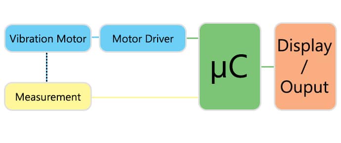
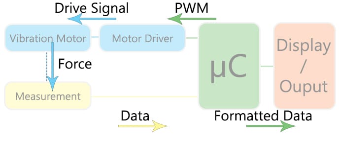
There are three main tasks for testing the motor. First, we need to drive it, then measure the output, and lastly, we need to display the data in a meaningful manner. There are lots of methods for each step we’ll suggest an easy and inexpensive way to tackling each.
Our basic system looks like this:
Driving the Motor
For a quick test, we have access to lots of motor drivers, in this instance, we used a breakout board for the Fairchild FAH4830. It’s extremely easy to drive DC motors with it, as it only requires a single PWM signal – although it has other inputs for additional features.
It’s likely that you already have a circuit for driving the motor so this shouldn’t be an issue. If you don’t, an equally easy equivalent is a single MOSFET and PWM signal, but in either set-up, you will need a microcontroller to create the PWM signal – we’ve used an Arduino.
If you’re truly in a rush, simply connect the motor to a battery to turn it on. However the next section is built around an Arduino/microcontroller, so it is highly recommended.
Vibration motors start-up quickly – even quicker when using haptic drive signals. This means you don’t need to drive it for long, you’ll quickly gather too much data if you drive it for a long time, try 100ms at first and you can tailor it later. Arduino handles PWM with the analogWrite(); function.
Measuring the Vibration
Use a specialised component called an accelerometer – a variety of chips and evaluation boards are widely available online and through local retailers.
In this test, we’ve used an MMA7361 triple-axis accelerometer from Freescale, mounted on a PCB with several external components to simplify use. This particular device works using switched capacitor techniques, the datasheet has a full principle of operation section if you’re interested.
You must mount the vibration motor and the accelerometer together. The more secure the mounting the better your results, read about how vibrations are transferred here.
If possible, mount the two to a mass with a known overall weight – the target mass has a direct influence on the resulting (measured) vibration amplitude. Check our vibration motor datasheets to see the mass of the test sled, given as the Rated Inertial Test Load. Almost our entire range uses 100g sleds (some stronger motors use a mass up to 1kg).
Once you have the vibration motor and accelerometer mounted a known weight, it is best to suspend this unit to maximise the mechanical isolation. For example, the motor lying on your desk will be influenced by the desk itself – it won’t be able to displace the desk’s surface. The more freely the unit can move the better, so a section of foam is better than a hard surface, but suspension is the best:
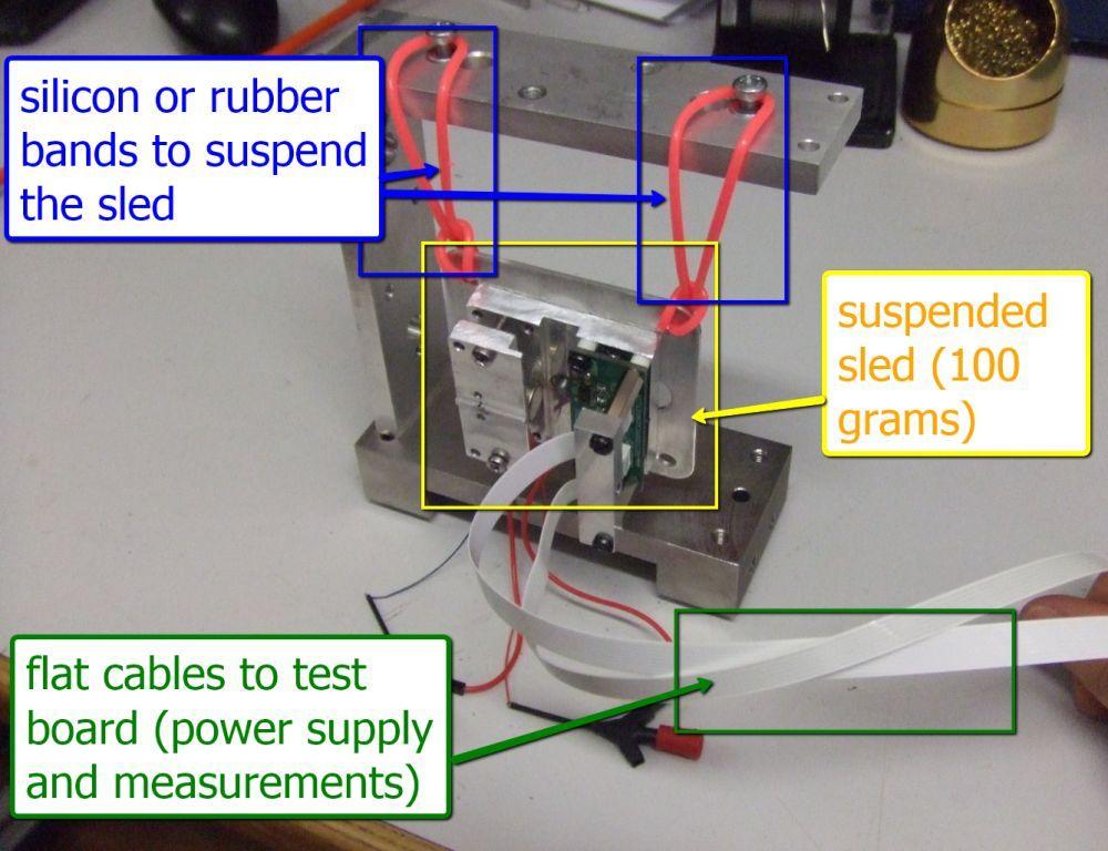
We’ve used silicon bands to hold the unit if you’re really stuck try, elastic bands. They aren’t ideal because when stretched they store a lot of energy and will affect the results – but they’ll work as a quick fix.
You also need a way of reading the output from the accelerometer, which will depend on your specific device. Our MMA7361 outputs three variable voltages, one representing the acceleration on each axis. We read these voltages using the analogRead(); function, which returns an int between 0 and 1023 which represents a voltage between 0 and 5 V.
Displaying the Data
At this point, we can drive the motor and are measuring the output of the accelerometer with our Arduino – but how can we display this data so it is useful?
The easiest method is to use the USB port on the Arduino and capture the information using a program running on the PC.
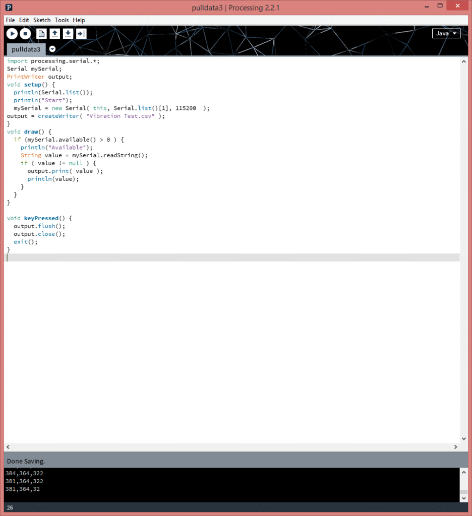
Using the Arduino’s Serial functions we can send the data up on the USB, formatted for saving as a .CSV file. We can easily write a program using a free piece of software called ‘Processing‘ to monitor communications on the serial port of our Arduino, and save any data to a file:
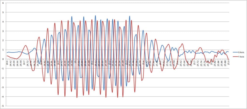
Once the data is stored in the .CSV file, manipulating it to display a graph requires some basic spreadsheet skills (if you’ve reached this point, the graph should be easy!):
Processing Code
Ok, so how do you actually do it! We’ll we’ve included the Processing code in a zip file which you can download here:
Vibration Measure Processing Code
Important notes about the code:
- Make sure the baud rates match! That’s the number in the
Serial( this, Serial.list()[COMPORT], BAUDRATE);function must match your Arduino’sSerial.begin(BAUDRATE);value - Make sure the COM ports match! The COMPORT in the function above is the port of the Arduino if you’re not sure what value to use try the
println(Serial.list());function. - The program saves the data to a file called “Vibration Test.csv”, this will write it immediately into a CSV file format to open in spreadsheet software
- Do not omit the
keyPressed()function, the data will not be written to the file without the flush and close of the output! Which means you have to stop the program by pressing a key on the keyboard – not clicking the stop button! - It also prints data on the serial monitor, this is useful for debugging as you can see data is being received. If nothing appears here then you have a problem with your hardware or Arduino code.
As stated at the top – this is a very quick and very rough method. For any detailed analysis, why don’t you contact us to see if we can help test your system?

Get in touch
Speak to a member of our team.
Motor catalogue
Looking for our products?
Reliable, cost-effective miniature mechanisms and motors that meet your application demands.
Discover more
Resources and guides
Discover our product application notes, design guides, news and case studies.
Case studies
Explore our collection of case studies, examples of our products in a range of applications.
Precision Microdrives
Whether you need a motor component, or a fully validated and tested complex mechanism – we’re here to help. Find out more about our company.