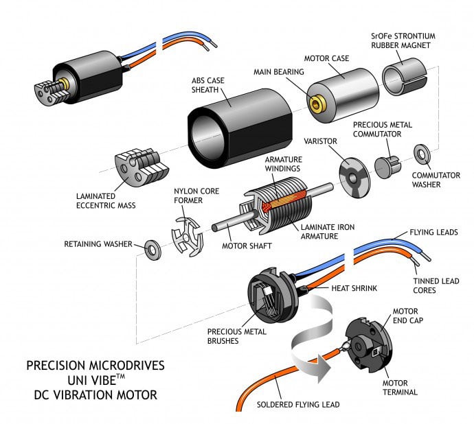
A Short Illustrated Primer On Brushed DC Motors
A brushed DC motor is an electromechanical motor driven by a DC power source. The basic parts of a brushed DC motor are:
- Case, bearing and stator magnets (stator, i.e. stationary),
- Motor shaft and washers,
- Armature / rotor,
- Commutator (and sometimes a Varistor), and
- Brushes and terminals or leads.
The diagram below shows this layout in an exploded view of a typical DC motor – in this case, a small Ø12mm vibration motor.
General Construction For A Y-Axis LRA Linear Vibrator
The illustration above shows the general arrangement of parts within a Y-axis LRA vibration motor. Those readers familiar with audio engineering will note that the voice coil drive is very similar to that loudspeaker. However, instead of a cone that generates sound pressure waves, there is a mass that generates vibrations.
Below is another LRA which works in the same way, however, the vibrations are directed in only the Z-axis. This offers users a greater choice in design as they can produce vibrations in either horizontal or vertical directions.

Get in touch
Speak to a member of our team.
Motor catalogue
Looking for our products?
Reliable, cost-effective miniature mechanisms and motors that meet your application demands.
The Armature is mounted on the shaft and has windings terminated to a commutator (sometimes with a varistor to reduce electromagnetic interference from commutator sparking); motor terminals (or leads) are connected to the motor windings through the motor brushes.
The stator magnets will have at least two permanent magnet poles. The electromechanical motor is designed such that opposite magnetic fields of the energised windings and the stator magnets cause the shaft to rotate. When the armature is aligned with the stator magnets, the brushes, which are also fixed to the motor case, will connect to the next commutator segment and thereby energise the next winding. This will change the magnetic field of the armature, which causes the motor to continue rotating. The diagram below shows the stator, armature and commutator geometry in more detail.
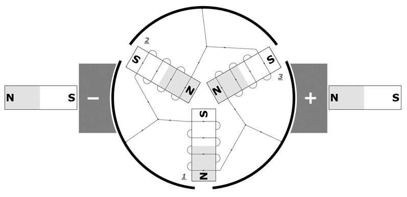
Two-pole brushed motors have two big problems. The first is that when the rotor poles and the stator poles are in line the torque is zero and the motor cannot start from this position. The other problem is that during the motor revolution, there is a moment where the brushes touch both the commutator sections. This leads to a short circuit of the inputs, a condition that can damage the power supply and reduce efficiency.
For this reason, most small electromechanical DC motors have a minimum of three poles. The rotor has three windings that are wired in a triangle (delta) configuration to the three sections of the commutator. The brushes touch two opposite sides of the commutator and, depending on the rotor angle, will energize the three coils in turn. The wiring and the position of the windings are designed to always create a force moving the rotor in a particular direction given a constant brush polarity.
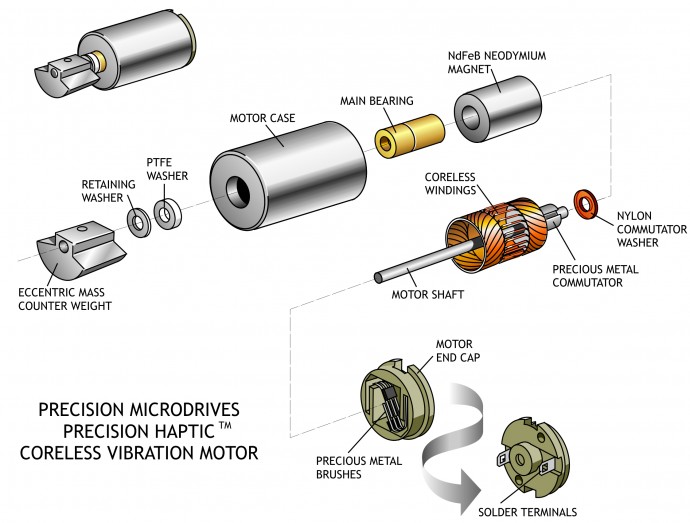
There are two main types of construction for small brushed DC motors: coreless and iron core. The use of an iron core rotor is very common for motors above 10mm in diameter. The coils are winded on a laminated iron core; this gives them rigid support and helps to dissipate heat. Drawbacks are the inertia generated from the iron core mass and the high coil inductance that limit brushes and commutator life.
Motors of diameter 10mm or smaller are usually realised using a coreless construction – an exploded diagram of this construction is detailed below. In this case, the windings by themselves create the rotor structure. The rotor is hollow and the stator magnet can be placed in the centre, saving space, reducing the inductance and increasing the heat dissipation (since the windings are closer to the case/outside of the motor).
Discover more
Resources and guides
Discover our product application notes, design guides, news and case studies.
Case studies
Explore our collection of case studies, examples of our products in a range of applications.
Precision Microdrives
Whether you need a motor component, or a fully validated and tested complex mechanism – we’re here to help. Find out more about our company.