Tachometers vs Encoders – What’s the Difference?
As it is possible for tachometers to perform the same basic function as encoders, it’s common to find that sometimes there is a bit of confusion between the terms. This can often lead to ‘over-design’ or ‘over-engineering’ because there is a wide range of complex encoders available, but a simple tachometer will often get the job done.
But first, let’s look at what each device does. In short, both tachometers and encoders are designed to provide some information about the movement of a motor shaft.
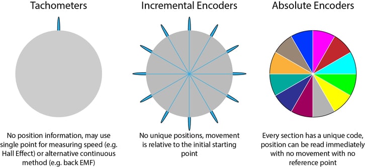
Tachometers measure speed and encoders measure position.
Tachometers
A tachometer will enable you to calculate the RPM of a motor.
As an analogy, if you can imagine a trundle wheel (ignoring the fact they’re actually designed to measure distance), they make an audible click once every full revolution. Count the time between clicks and you can figure out how fast the wheel is spinning – or its RPM.
There are lots of ways to achieve this, you might make use of the Hall Effect to measure every time the motor makes a full revolution or some other mechanical method. Many of the measurement techniques are similar to encoders, however, encoders typically aim for a much higher resolution, making them more complicated. The benefit of a tachometer is its simplicity, you only need one measurement per rotation.
In fact, DC motors create a back EMF when they rotate which can be measured, so you can build a tachometer out of discrete electronic components. If you’re interested in measuring the back EMF see this application bulletin, but we also have an AB on sensorless DC motor control that you can read here.
Encoders
There are two main encoder types that help tell you about the position of the motor shaft. One simplification that we’ve made is that we’re only discussing single turn encoders. Multiturn encoders, where we are able to determine the shaft’s position beyond a single rotation, would require a much more in-depth discussion about encoders in general.
Incremental Encoders
Incremental encoders are the simpler of the two types. They provide a reading every time the motor shaft rotates a certain distance. Think of a playing card clipped or glued to a bike frame, with one end in the spokes of the wheel. As the wheel turns, the card hits the spokes and makes a noise. If we know the angle between spokes and can count every time the card makes a noise, then we can figure out how far the wheel has turned.
This is very similar to the idea of an incremental encoder. Obviously, with more measurement points (or ‘spokes’ in our analogy) we can increase the accuracy of our calculation. However, note that there is no information about the actual position of the wheel – only relative to the starting point. For this reason, some applications might use a start-up algorithm that takes the rotor to a known position.
In many instances, a starting algorithm simply isn’t possible – for example when power is intermittent or the motor cannot go to extremities, like in a locking mechanism. Here, absolute encoders are preferred.
Absolute Encoders
Conversely, absolute encoders do provide an exact position of the motor shaft. There are various types of measurement used (beyond the scope of this blog post), the most common are optical and magnetic-based readings. In each method, the processor is able to calculate the exact position of the motor shaft with surprisingly high accuracy.
The big difference is that because each angle section is uniquely coded, the shaft position is not relative to any other point. So there’s no need for a starting algorithm and the position can be determined immediately with no need for movement.
Of course, as we mentioned at the start encoders can be used as tachometers, as measuring a full revolution is essentially measuring the position of the shaft – just with very poor resolution! In fact, using an encoder as a tachometer does offer the benefit of improved dynamic response, you do not need to wait for a full rotation to update your measurement and can determine the speed of a motor with greater accuracy.
For this reason, the choice of ‘tachometer vs encoder’ isn’t quite as clear-cut as you might expect. That’s certainly one area where we can help – design advice and guidance is easy to get from our engineers. Also, we’re happy to undertake design work for you, even overseeing manufacturing and ongoing testing, simply let us know your application to ask for help.

Get in touch
Speak to a member of our team.
Motor catalogue
Looking for our products?
Reliable, cost-effective miniature mechanisms and motors that meet your application demands.
Discover more
Resources and guides
Discover our product application notes, design guides, news and case studies.
Case studies
Explore our collection of case studies, examples of our products in a range of applications.
Precision Microdrives
Whether you need a motor component, or a fully validated and tested complex mechanism – we’re here to help. Find out more about our company.