AB-017
Integrated Driver Circuits For Vibration Motors
Introduction
We have previously offered advice on how to reduce voltage supplies to appropriate levels in Application Bulletin 011, and using a regulator of motor driver chip was one suggestion. We have also produced Application Bulletins looking at discrete driver circuits and how to drive linear resonant actuators. Here we finally cover a range of chips specifically designed for driving vibration motors.
Using a dedicated chip has a number of advantages, the most obvious being a reduction in design complexity, and each individual device has its own characteristics which may benefit your design.
Here we cover the three most popular chips, however, if one of these does not satisfy your requirements there are others available on the market.

Get in touch
Speak to a member of our team.
Motor catalogue
Looking for our products?
Reliable, cost-effective miniature mechanisms and motors that meet your application demands.
Why Use A Vibration Motor Driver?
If your application requires the vibration motor to be controlled by a processor or microcontroller, including PWM or logic signals, then you will need extra circuitry around the motor. These signal sources sometimes have too low a signal voltage and certainly cannot provide enough current. This is particularly true for processors which have maximum current levels on output pins of under 40 mA (typically), whereas a typical small vibration motor has a Typical Operating Current of 70 ~ 100 mA.
So how do engineers use processors to control vibration motors? The simplest is to use discrete transistors or MOSFETs and to see how to do this, you can take a look at Application Bulletin 001. Others use a regulator integrated circuit (IC). The simplest way is to use a dedicated motor drive IC which can provide the vibration motor with the voltage and current required, and the internal electrical protection required to perform reliably. These IC’s are invariably connected to the motor to the main power source, often via some regulation, and use logic or PWM drive signals from the controller to turn the motor on and off.
In addition, there is an internal protection. Back EMF and other electromagnetic interference generated by the motor can damage components some components, which can be minimised or solved by using additional components and best design practices; for example, see AB-005: Electromagnetic Compatibility (EMC / EMI) with Vibration Motors for guidelines. However, many driver chips include internal protection and act as a buffer between the ‘noisy’ motor and the control circuits. This often leads to reduced component count less PCB space being used.
In fact, there are many problems / advanced motor drive techniques/features which we have discussed in our Application Bulletins which apply to implementations using specific motor drive IC’s. Here’s a quick list of our Application Bulletins that recommend or could benefit from using a designated driver chip:
- AB-001: Discrete driver circuits for vibration motors
- AB-002: Discrete H-bridge circuit for enhanced vibration motor control
- AB-005 : Electromagnetic Compatibility (EMC / EMI) with Vibration Motors
- AB-008: Vibration Motor Best Practices from the Mobile / Cell Phone Industry
- AB-011: Electrical Techniques for Using Different Power Sources
- AB-012: Driving Vibration Motors with Pulse Width Modulation (PWM)
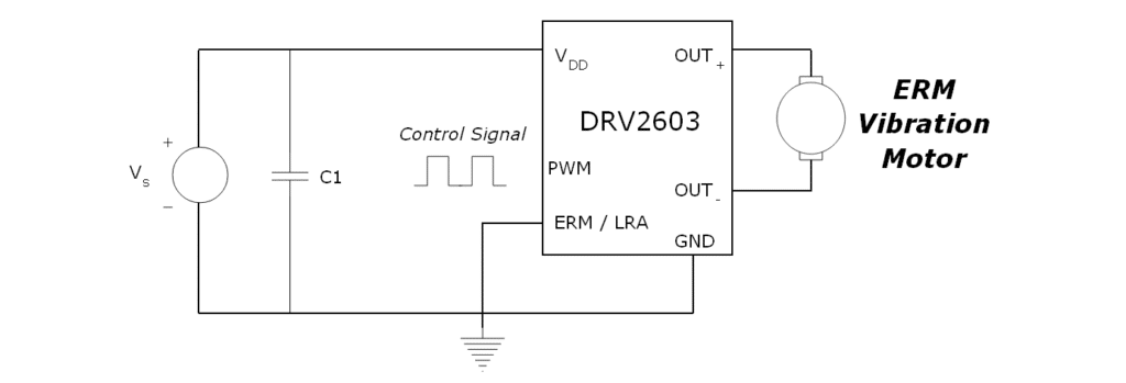
Texas Instruments – DRV2603 – LRA / ERM Driver
This chip is new on the market and can drive either ERMs or linear resonant actuators depending on the connection of the ‘mode’ pin. Because it contains a differential single supply amplifier, it makes it easier to create advanced vibration alerting and haptic feedback waveforms.
With its own internal control engine, it accepts a PWM signal where the duty cycle controls the direction and speed of the motor. At 50% there is no drive force applied to the motor, while 100% turns the motor at full strength in one direction (e.g. clockwise) and 0% would turn the motor at full strength in the opposite direction (e.g. anti-clockwise). This is achieved by implementing a full H-bridge circuit inside the chip.
The benefit of being able to drive the motor in different directions is increased haptic and vibration performance. In order to generate that ‘crisp’ feeling in a click or button press, the motor needs to be stopped or ‘braked’. This is achieved by reversing the input voltage to the vibration motor, and therefore the DRV2603 can easily generate this effect.
This means simple programming in software can produce fairly advanced waveforms, such as those discussed in AB-014: Advanced Vibration Alerting Waveforms. It also means an array of waveforms can be stored in memory to be called upon, and this would not take up much space as each waveform only needs to store values of duty cycles.
As the IC contains most of the components required, the footprint and complexity of the vibration motors circuit is greatly reduced. In fact, the DRV2603 only requires a decoupling capacitor at the power pin, and we’ll see this is common for the other drivers later in this bulletin.
One final thing to note about the DRV2603 is that it has an auto-resonance feature for driving Linear Resonant Actuators. LRA’s resonant frequency can drift with temperature and age and the DRV2603 uses back-emf measurements to adjust the drive frequency slightly to keep it working optimally.
You can download the datasheet for the DRV2603: DRV2603 DATASHEET
ON Semiconductor – NCP5426 – LDO Regulator / Vibration Motor Driver
The NCP5426 is a low dropout LDO linear regulator which has been specifically designed for driving vibration motors, although it can be used for other applications. Unlike the DRV2603 it can only drive the motor in one direction, meaning it lacks the ability to create advanced vibration waveforms.
It works in a similar method to using a MOSFET as a switch, except the output voltage is not determined by the voltage from the power supply (Vin) and instead has a predefined fixed output voltage.
This fixed voltage approach makes it easy to use a vibration motor that has a much lower rated voltage than the power supply. The NCP5426 can accept an input voltage as high as 12 V and the enable pin is switched on with a voltage of 1.6 V, allowing it to be easily controlled with a microcontroller or other low voltage signal.
However, as the output voltage is defined internally the chip is less flexible than other solutions. Variants are available (in 0.1 V increments) that have an output voltage between 1.2 V and 2.0 V. This means the driver is suitable for around half of our Pico Vibe™ range, but rules out the use with our coin vibration motors or the Uni Vibe™ range, both of which need higher drive voltages.
The circuit for the NCP5426 is extremely simple:
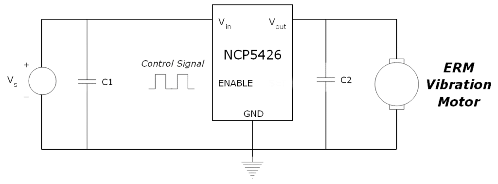
The two components C1 and C2 are decoupling capacitors. The application information on the datasheet recommends ceramic or tantalum capacitors, and that C1 should have a relatively high value and 1.0 uF as a minimum. There is no additional circuitry required, making it a very small sized low cost solution. Download the datasheet: NCP5426 DATASHEET
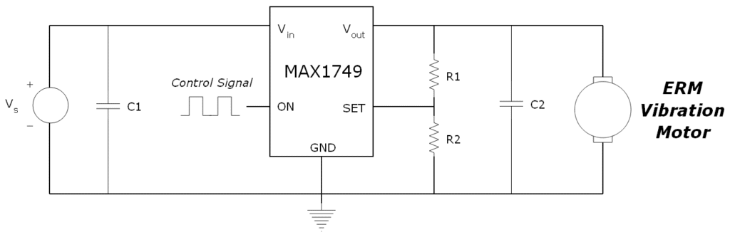
The MAX1749 has a much wider output than the NCP5426 above, with a minimum of 1.25 V and a maximum of 6.5 V. This means it can be used with most of our Uni Vibe™ range, in addition to the full Pico Vibe™ range. However, it is also not a full H-bridge circuit and cannot drive the motor in each direction. This limits its useful scope to vibration alerting functions.
It is based on a simple MOSFET design, but instead of having a fixed output voltage, it can be adjusted using a potential divider circuit around the ‘SET’ pin. This has its advantages and disadvantages. For prototyping, it allows for an easy change of the output voltage, which can allow engineers to test a variety of different output motors. Or when the same internal drive circuitry is to be used on several different products which have different vibration motors, the same chip can be used to drive all the motors, even if they have different rated voltages. Conversely, the extra required components and manufacturing may be undesirable.
It is worth noting that the MAX1749 also requires additional decoupling capacitors as seen in the circuit diagram below:
Other features for the driver include thermal overload and reverse battery protection to ensure the device’s safe operation. Take a detailed look at the datasheet: MAX1749 DATASHEET
Conclusion
Vibration motor integrated driver circuits can reduce the complexity of a system whilst enhancing the performance of the device. In many cases, they can solve multiple problems that face designers when using vibrating motors with digital control signals in a small package.
They can help control power supply regulation, provide the motor with required current / voltage, improve EMC performance, protect the microcontroller, all whilst ensuring the motor is accurately controlled. They can even simplify the software design by using a single PWM signal to generate more advanced vibration waveforms.
Different chips may have advanced features and there are different types available for every application. We have covered three different ICs, each with its own merits and varying capabilities. Example circuits and datasheets are available throughout this Application Bulletin.
Newsletter
Sign up to receive new blogs, case studies and resources – directly to your inbox.

Sign up
Discover more
Resources and guides
Discover our product application notes, design guides, news and case studies.
Case studies
Explore our collection of case studies, examples of our products in a range of applications.
Precision Microdrives
Whether you need a motor component, or a fully validated and tested complex mechanism – we’re here to help. Find out more about our company.