Coin Vibration Motors
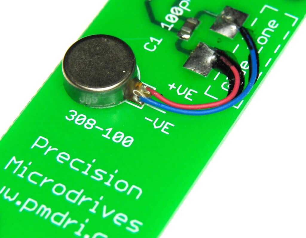
Precision Microdrives currently produces coin vibration motors, also known as shaftless or pancake vibrator motors, generally in Ø8mm – Ø12mm diameters for our Pico Vibe range. Pancake motors are compact and convenient to use. They integrate into many designs because they have no external moving parts, and can be affixed in place with a strong permanent self-adhesive mounting system.
Enclosures can easily be moulded to accept the coin form of our shaftless vibration motors. Within the coin motor range, we offer both leaded and spring & pad mountable versions. Like all of our vibration motors, we are happy to quote for variations to the base design such as a modification to the lead length and also connectors.

Get in touch
Speak to a member of our team.
Motor catalogue
Looking for our products?
Reliable, cost-effective miniature mechanisms and motors that meet your application demands.
Applications
Due to their small size and enclosed vibration mechanism, coin vibrating motors are a popular choice for many different applications. They are great for haptics, particularly in handheld instruments where space can be at a premium:
- Mobile phones
- RFID scanners
- Industrial tools or equipment user interfaces
- Portable instruments
- Medical applications
General Layout And Operation
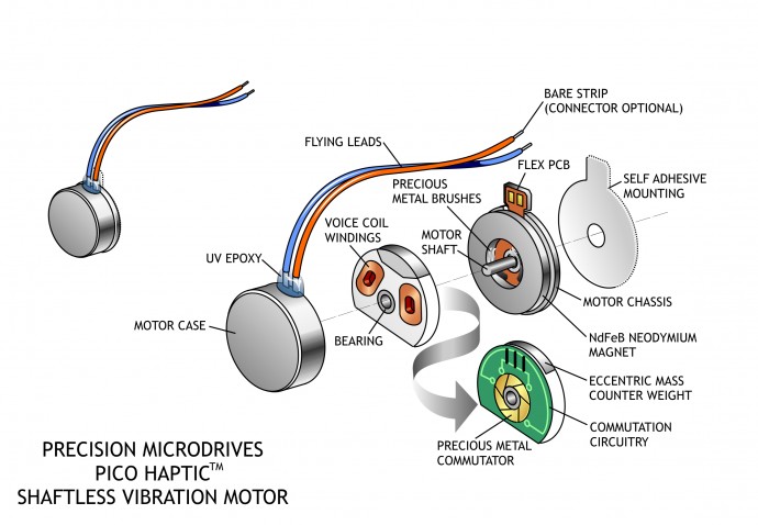
Our coin or pancake vibrating motors are all Eccentric Rotating Mass (ERM) motors. Therefore they can be driven in the same manner as their pager motor counterparts. They have the same motor drive principles, including H-bridge circuitry for active braking.
Brushed coin vibration motors are constructed from a flat PCB on which the 3-pole commutation circuit is laid out around an internal shaft in the centre. The vibration motor rotor consists of two ‘voice coils’ and a small mass that is integrated into a flat plastic disc with a bearing in the middle, which sits on a shaft. Two brushes on the underside of the plastic disc make contact to the PCB commutation pads and provide power to the voice coils which generate a magnetic field. This field interacts with the flux generated by a disc magnet that is attached to the motor chassis.
The commutation circuit alternates the direction of the field through the voice coils, and this interacts with the N-S pole pairs that are built into the neodymium magnet. The disc rotates and, due to the built-in off-centred eccentric mass, the motor vibrates!
Equivalent Coin Motor Circuitry, Commutation, Terminal Resistance
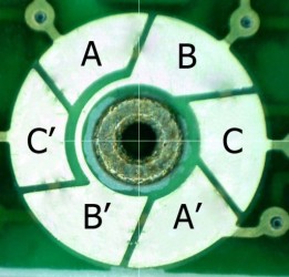
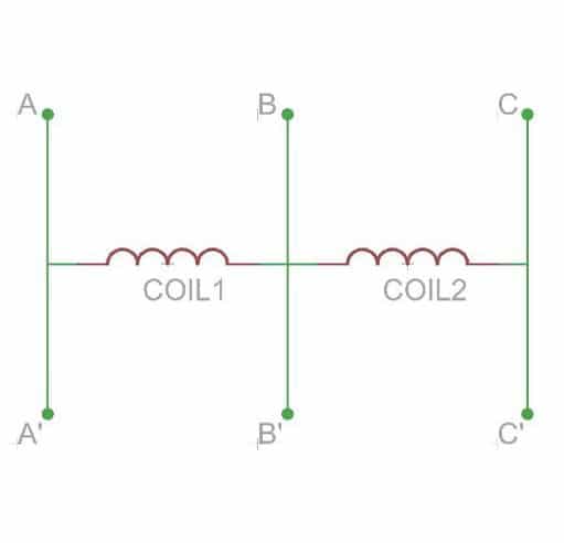
The commutator is formed by 6 segments connected to two coils. The equivalent circuit is shown on the right. The coils can be magnetized in 6 different ways, effectively making this a 6 pole machine. However, a peculiarity of this commutation design is that during one rotation the resistance through the brushes is not constant.
For a third of the revolution the brushes “see” the two coils in series instead of only one; which is why in some orientations the resistance seen by a circuit will be double and therefore the start current half the rated value.
The current figures presented in Conformity Limits Specifications sections of datasheets represent the worst case current draw; i.e. where the brushes see only one coil.
Start Voltages And Drive Signals
The full term ‘Maximum Start Voltage’ is the lowest voltage that you can apply to the motor and still be sure that it will start.
Coin vibration motors have a relatively high start voltage (compared to cylinder pager vibration motors) which must be considered in designs. Typically this is around 2.3v (all coin vibration motors have a nominal voltage of 3v), and failure to respect this could result in motors not starting when the application is lying in certain orientations. This problem arises because, in the vertical orientation, the coin vibrating motor must force the eccentric mass over the top of the shaft on the initial cycle.
Due to the start voltage issue, we recommend that coin type vibrating motors are switched hard on and off at a voltage above the guaranteed start voltage unless a well-tested haptics driver is used.
Mounting
Coin vibration motors are designed to be easy to mount. They come with either spring PCB connectors or a high-strength long life self-adhesive backing sheet that is pre-attached to the underside of the chassis. The adhesive allows for a secure mounting of the vibration motor to a wide range of surfaces such as PCBs or flat internal surfaces of the enclosure and makes manufacturing installation fast and clean.
Three brands of adhesive are typically used on our coin vibrator motors depending on availability (they all have very similar specifications).
These are:
- 3M VHB 9448
- Sony 4000T
- Nitto 5000NS
These 0.16mm thick adhesive tapes typically offer a 180 deg peeling strength of 15N/20mm, and a tensile strength of around 20N/10mm. The acrylic adhesive is considered to be resistant to most solvents, UV light, moisture and temperature extremes.
As with all adhesives, the final bond strength is dependent on the cleanliness of the mating surface. It is recommended that this mating surface is clean, dry, and offers a good unified fit to the motor backing-plate (on which the self-adhesive pad is stuck).
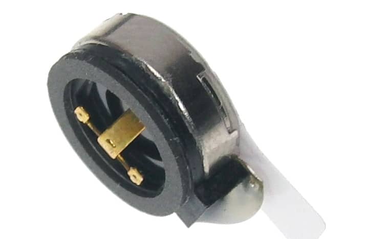
Spring PCB vibrator motors have spring-loaded fingers on the motor which mat with pads on the PCB. This makes assembly easier for applications where it’s desired to have the motor mounted to the enclosure. Also, higher frequency harmonics are absorbed and reduced by the rubber ‘boots’ that enclose these kinds of motors.
If extra security is required, consider the moulding securing walls within the enclosure body. This technique is commonly used in mobile phones to ensure that the maximum amount of vibration is transmitted through the case.
Leads & Connectors
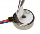
Our stocked range of ‘pancake’ motors generally come with flying leads, although some models are available with sprung gold terminals that sit on top of the motor (shown right). This pancake vibration motor is designed to be fitted to the enclosure. The springs mate with pads on the motherboard PCB which makes the connection, which is a neat way to avoid routing flying leads around the case if there is PCB real-estate available. You can read more on spring & pad vibration motors as part of our PCB mounted vibration motor pages.
If you need guidance on how best to mount or connect any of our coin vibrator motors within your application, please don’t hesitate to contact our engineering support team, who will be happy to help.
Discover More
Resources & Guides
Discover our product application notes, design guides, news and case studies.
Case Studies
Explore our collection of case studies, examples of our products in a range of applications.
Precision Microdrives
Whether you need a motor component, or a fully validated and tested complex mechanism – we’re here to help. Find out more about our company.