AB-005
Electromagnetic Compatibility (EMC / EMI) For Vibe Motors
Overview
Electromagnetic interference (EMI) is the radiation or induction of electromagnetic noise on a system. DC motors are a common source of EMI, as are most electromagnetic circuit components. They are potential sources of noise and can generate common-mode currents. EMI can result in degraded performance, data corruption, or if strong enough can cause the system to fail completely. EMI can be radiated or conducted comes from magnetic and electrical sources, respectively. In the case of DC motors, both radiated and conducted emissions are present.
Electromagnetic compatibility (EMC) is the practice of monitoring and reducing unwanted EMI. There are often varying regulations on EMC, depending on the purpose of the system and the country it is used or sold in. For example, you can read about the EU’s EMC regulations here. EMC performance concerns the complete system or final product and is therefore usually the responsibility of the OEM (original equipment manufacturer) and not of those who supply the components. Here we will show you some popular EMI reduction techniques for motors to improve your systems EMC performance.

Get in touch
Speak to a member of our team.
Motor catalogue
Looking for our products?
Reliable, cost-effective miniature mechanisms and motors that meet your application demands.
The Generation Of EMI
Arcing (sometimes referred to as arc discharge or voltaic arc) is an electrical characteristic where current can flow through the air or other normally non-conductive materials. You may have seen instances of arcing between two wires, or on the power rails of trains or trams. This is not to be confused with an electrical spark, as an electrical arc is continuous, however, they do look alike.
Whilst arcing can be useful, used in both welding and strip lighting, in some cases, it can be a source of EMI. In DC motors, arcing can be common because of the periodic interruption of the current in the rotor windings. This very high-frequency spectra content, which can appear as wideband noise superimposed onto other signals. DC motors also provide paths for common-mode currents through their frames.
An additional source of radiated and conducted emissions can come from the driver circuit. A typical H-bridge circuit should ideally provide a constant current to the motor, but this current has fast rise time spikes due to the fast and frequent switching of the current in the driver circuit. Another significant problem is that usually the motor is quite far from the driver, and this creates a fairly large loop area between motor leads and device frame. The radiation potential is a direct function of the loop area; the larger the loop, the larger the emissions.
How To Reduce EMI And Improve EMC
Common-Mode Current Reduction
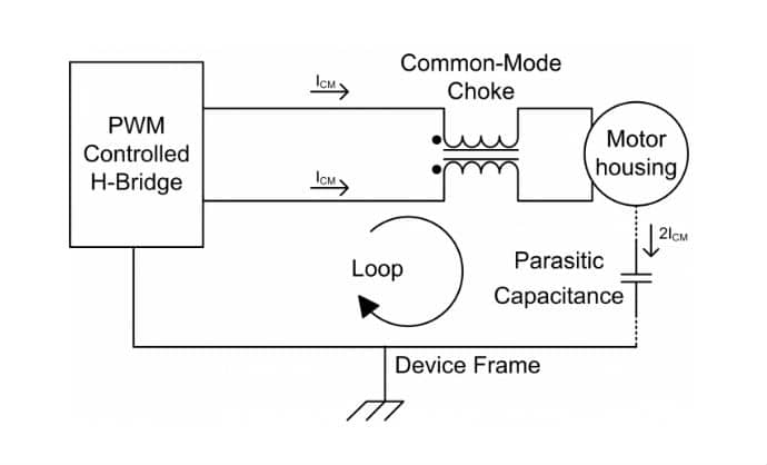
To block the common-mode current, a common-mode choke could be placed in the motor leads, as shown in the figure below.
Chokes are used extensively in the cell / mobile phone market; you can read more about this in our analysis of mobile phone vibration motor implementations.
Radiated And Conducted Noise Reduction
Standard Components
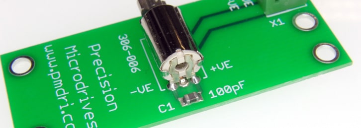
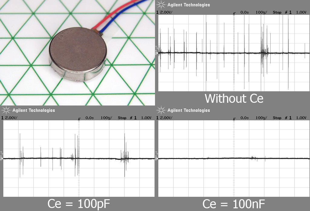
The easiest solution is to place a ceramic capacitor between the motor terminals, as close as possible to the motor. This is known as a decoupling capacitor and reduces EMI by removing some of the high-frequency noise signals. The common value used for these decoupling capacitors is between 100pF and 100nF, depending on the size of the motor. There is an example picture at the top of the bulletin, and some example test results are shown below.
If a PWM signal is used for motor control, the capacitor should be chosen to have a resonant frequency with the motor inductance far from the PWM frequency. A value between 10 and 100pF is usually correct. The resonant frequency ( f_{r} ) is calculated as:𝑓𝑟=𝑓𝑟𝑎𝑐12𝑝𝑖𝑠𝑞𝑟𝑡𝐿𝑚𝐶𝑒
Where ( L_{m} ) is the motor inductance and ( C_{e} ) is the external decoupling capacitor. For motors with low terminal resistance, an additional resistor in series with the capacitor will help with the dumping.
A more comprehensive solution involves two additional capacitors to the one above, one per motor terminal, connected between the terminal and motor housing. This will reduce the arcing, especially for carbon brush motors.
X2Y Attenuator
A number of more complex filters can be implemented with inductors, capacitors, and varistors as elements. A simpler, cheaper, and more effective solution can be implemented by a single X2Y® attenuator. The following PDF is an application note that describes the X2Y® attenuator operation and implementation, together with tip and trick to minimize the emissions from a DC motor.
More publications and a list of manufacturers can be found on the X2Y® Attenuators website.
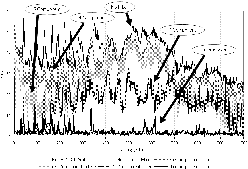
The graph below shows the emissions from a 27mm 12V DC motor in different conditions. The best results (lowest emissions) are obtained when an X2Y® attenuator is fitted (1 Component track on the graph). The PDF under the graph describes the test performed and the types of filter used.
Grounding Securing Pads For PCB Mounted Vibration Motors
A small improvement in EMC can be seen if the securing pads of the PCB-mounted vibration motors are tied to the ground. This grounds the case and the internal components which can help act as a shield to the commutation mechanism. It’s not perfect though because EMI will still leak through the plastic end-cap; so you can’t use it as a substitution for component-based EMC suppression.
Conclusion
EMC is an important field in electronics with strict regulations, and DC motors and their circuits are significant sources of EMI. It is therefore essential that engineers take the appropriate actions to reduce EMI and improve EMC as much as possible. We have suggested several common techniques to achieve this with simple additional circuitry.
Newsletter
Sign up to receive new blogs, case studies and resources – directly to your inbox.

Sign up
Discover more
Resources and guides
Discover our product application notes, design guides, news and case studies.
Case studies
Explore our collection of case studies, examples of our products in a range of applications.
Precision Microdrives
Whether you need a motor component, or a fully validated and tested complex mechanism – we’re here to help. Find out more about our company.