AB-015
Mechanical Mounting For Vibration Motors: Moulded And Machined Enclosures
Overview
A common method for mounting vibration motors we have yet to cover is the use of receptacle mounting features in moulded or machined enclosures. With advances in plastic composition and increased injection moulded tolerances, these are now excellent options for mounting even the smallest of vibration motors such as our Pico Vibe™ range in highly integrated designs.
In this bulletin, we discuss several advantages for using moulded and machined enclosures and then look at a variety of design considerations which are important to the success of the enclosure.
This method is generally used for smaller handheld applications as the product is likely to already have a moulded body. This is unlike mechanical aid applications where the vibration motor might be mounted to a metal chute or hopper. If you are unable to find a suitable mounting method here, then you may wish to consider AB-007: Mechanical Mounting for Vibration Motors: to Bulkheads. Also if you happen to be considering mounting vibration motors to fabrics and materials, consider AB-010: Mounting vibration motors to flexible materials.

Get in touch
Speak to a member of our team.
Motor catalogue
Looking for our products?
Reliable, cost-effective miniature mechanisms and motors that meet your application demands.
Advantages And Benefits Of Using Moulded Or Machined Enclosures
Vibrations Transferred Directly To Casing
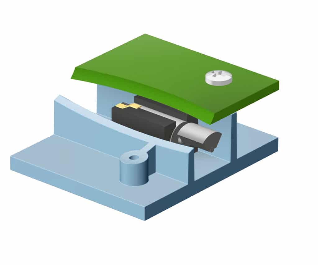
The basic principle behind moulded enclosures is that the motor is secured by direct contact with the casing. This can include either fully encapsulating the vibration motor in the plastic mould, or by pinning it down with another section of the device such as a PCB.
A major benefit of securing the motor in this way is that the vibrations produced by the motor are transferred directly into the casing. This is particularly useful for vibration alerting and handheld applications as the strength of vibration is not diminished through the transfer between motor to PCB, then PCB to the enclosure. It also reduces the risk of the mounting points on the PCBs being vibrated quite as much, which can sometimes cause unwanted rattles if the PCB isn’t screwed down.
If the motor is fully enclosed by the housing then our leaded vibration motors make it easy to connect to a remote drive circuitry, enabling the vibration motor to be placed in dedicated moulding which can be used to help isolate its source. We touch on this example application of a car dashboard equipped with haptic feedback in the previous Application Bulletin 014: Mechanical Layout of Vibration Motors for Typical User-Interface and Controls.
Using Spring Pad Vibration Motors
Spring pad motors are not as popular as they once were with the advent of surface mount motors which are easier to place, and since vibration motors designs have become more reliable, reducing the need for motors to be replaceable in some applications.
However, they are still used in high volumes, because they are the easiest of any motor to fit into a moulded receptacle. Of course, they are also much easier to replace and service compared to soldered equivalents if the application demands them. We have previously posted in our Tech Blog some interesting findings about the lifetime of our motors. The post shows how vibration motors, as with all DC motors and other electromechanical components, decay over their lifetime and eventually fail. For products with a service life beyond 5 years, a spring-pad motor with a plan to replace might be a sensible plan.
Another advantage over leaded motors (though not PCB mounted types) is that there are no leads and therefore no susceptibility to the metal fatigue problems that leaded vibration motors can suffer from. Although, metal fatigue isn’t a problem if construction is done correctly as illustrated in a previous application bulletin to this topic, see AB-009: Securing Vibration Motor Leads and Wires for more information.
Reduce Part Count And Assembly Costs
This is not the first time we have looked at using moulded housing for mounting vibration motors. In AB-006: Mechanical Mounting for Vibration Motors: to PCBs we discussed the option of using specially designed moulds for attaching the ERM motor to a PCB. These offer benefits but at add complexity and cost. The method requires a separate small plastic mould in addition to screws or cables to secure the mould down to the PCB.
Where possible, it is much more cost-effective to build these mounting features into the end product enclosure.
Design Considerations
Vibration Motor Fit
One of the most obvious design considerations is that the motor must be held secure. Unsecured motors produce audible rattles and that can make even the most expensive and well-designed application look cheap.
Furthermore, if the motor is loose, vibration can be transmitted to the joints of the electrical connections which can severely degrade their reliability. Finally, It is important to note that if the vibration motor is in any way ‘loose’, there will be a loss in vibration strength and haptic performance which undermine haptic feedback and vibration alerting applications.
We advise designers to aim for a 0.05mm interference between the motor outer dimensions and the inner dimensions of the plastic receptacle feature for a typical push fit. More beady-eyed readers will notice that general tolerances of motors are specified to +/- 0.2mm. In practice motors produced within the same batch rarely have variations anywhere near this, but sometimes small tooling/design changes are required which can affect inter-batch measurements and tolerances.
This is why the rubber ‘boot’ surround was invented. Some motor types (notably the spring pad types) come with rubber ‘boot’ surrounds which are designed to allow for a small amount of compression, ensuring a tight interference as motor and mould tolerances vary. If you want a feature like this in a production motor – ask us. Minimum order quantities will apply, but they’re generally in the thousands so within reach of many consumer and industrial applications.
Sometimes, despite best intentions, the tolerances of motor and plastic process will collude to create a larger feature gap that is beyond a ‘push fit’, and the motor will be loose. In these cases, filling adhesives are the best way forward. Epoxy and hot-melt are ideal.
Clearance For Eccentric Mass To Rotate
If you are using a standard ERM vibration motor then it is important that the mould leaves enough space for the eccentric mass to freely rotate. As it is the rotation of the mass that creates the vibrations, if the enclosure stops the mass then the product will not vibrate (see AB-004: Understand ERM Characteristics).
This is especially important for products which may have a soft plastic or rubber mould where the user’s grip or contact can alter the shape of the enclosure. A solution to this for regular ERM vibration motors is a hard encapsulation cap.
Another way of avoiding this issue is to use a vibration motor where the eccentric mass is not exposed. For example, we have several enclosed vibration motors and encapsulated vibration motors which both have casings which cover the eccentric mass. Coin vibrating motors are also enclosed, as are our linear resonant actuator which has a similar form factor.
Moulding Features
There are effectively two ways to ensure a snug fit of the motor within an injection moulded or specifically designed mounting position. One is to ensure there is a push fit interference between the motor body and the surrounding mounting features, and the second is to design a small gap and use an elastomeric material such as foam or rubber to maintain positive holding pressure on the motor. For moulded features, the common types include;
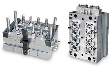
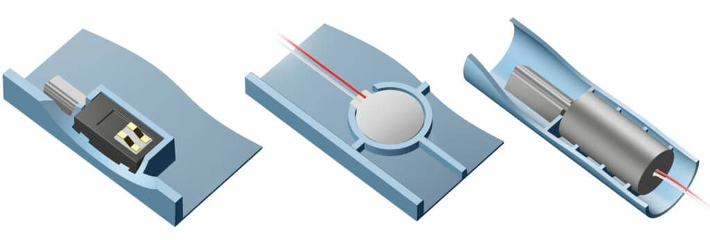
1) Structural ribs: Injection moulded enclosures usually include structural ribs to increase the part stiffness and strength while reducing material volume and part thickness. These structural ribs can be designed to fit the outer body of the motor so that one side of the motor is supported by a specifically formed series of ribs. The motor can be secured in position with an adhesive, securing fastener, or by using a clamshell enclosure where the two halves containing ribs will combine and secure the motor. The tolerances of structural ribs typically require elastomeric support unless the part is glued.
Notes: Rib features are susceptible to dimensional change by shrinkage during cooling for injection moulded parts. To minimise this effect it is important to consider the following:
- A minimum radius of 0.5mm is recommended for sharp corners where possible to avoid stress concentrators
- Rib base wall thickness should not exceed 50% of the adjoining wall thickness to avoid sink marks
- A minimum of 1-degree draft on rib features should be maintained to avoid difficulty with part ejection
- The fill and packing pressure should be sufficiently high to avoid cooling shrinkage
- Decreasing the melt temperature, and increasing the cooling time can be also used to avoid high-temperature differentials across the part cross-section.
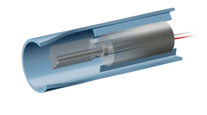
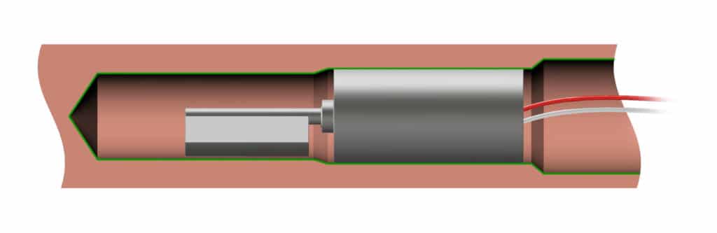
2) Push-fit cylindrical tube: For cylindrical ERMs, they can be supported by a dimensionally accurate cylinder into which the ERM can be push-fit. The use of adhesive or a mechanical securing method is recommended for this as the vibrations are likely to loosen the fit over time. The push-fit is a reliable method for assembling the vibration motor due to the simplicity of the process; additionally, as the motor is supported across the full depth of the body the transmission of the vibrations to the case is very good.
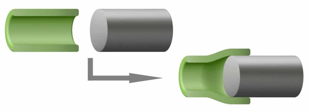
In most of the motors from us, the motor body diameter has a tolerance of +/- 0.2mm to account for batch-to-batch variation in the stamped motor case. It is important to be aware of this for push-fit assembly as the holding tube must maintain sufficient ductility to exert positive pressure for the different possibilities for body diameters.
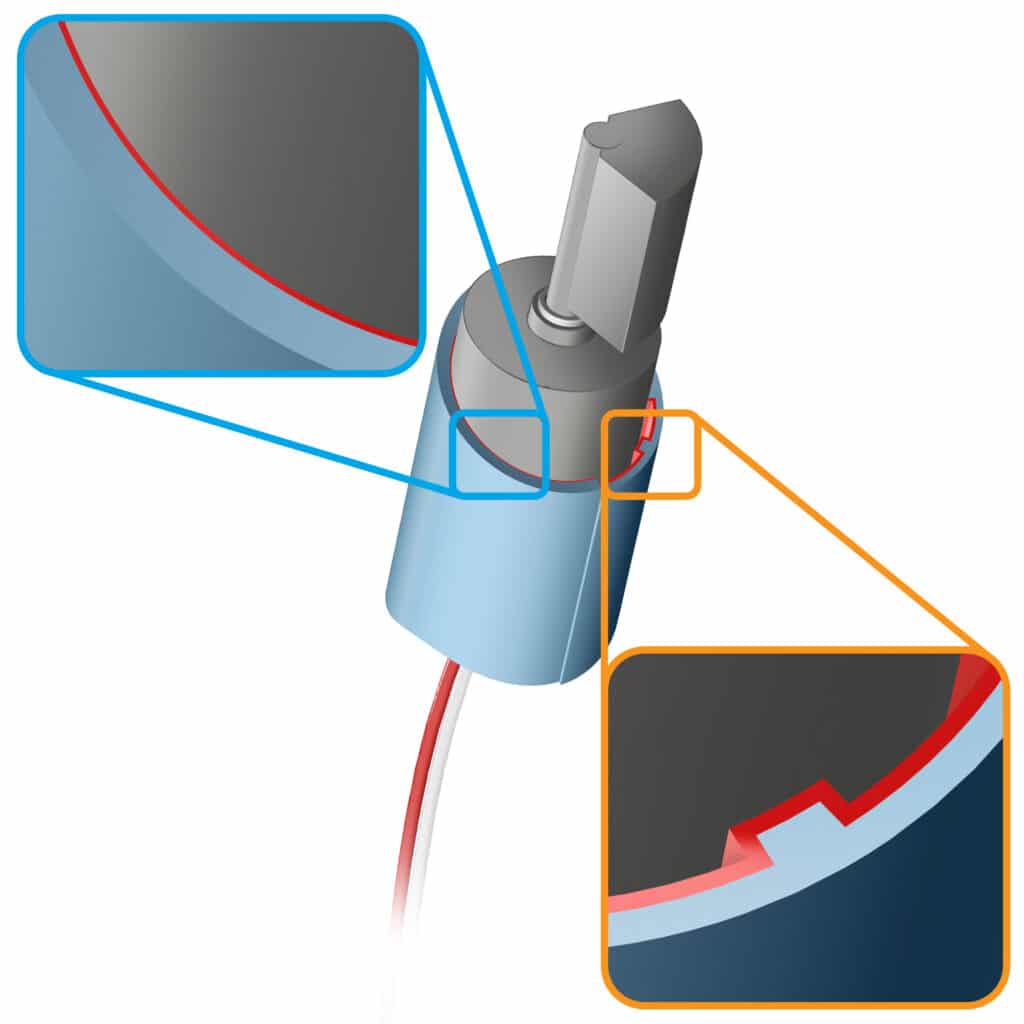
Allowing for tolerances for the push-fit feature can be achieved by:
- Avoid sharp edges or other stress concentrators to allow the material to expand to fit the motor without causing cracks
- Material choice for ductility and fatigue resistance
- Using crush ribs which deform on assembly
The equation for determining the allowable interference between a solid shaft and a hub is as follows:𝐼=𝜎𝑑×𝐷𝑠𝑊×[𝑊+𝑣ℎ𝐸ℎ+1−𝑣𝑠𝐸𝑠]
and𝑊=𝐷2ℎ+𝐷2𝑠𝐷2ℎ−𝐷2𝑠
Where:
- 𝐼 = Diametral inteference, mm
- 𝜎𝑑 = Design yield stress, MPa
- 𝐷ℎ = Outside diameter of hub, mm
- 𝐷𝑠 = Diameter of shaft,mm
- 𝐸ℎ = Modulus of elasticity of hub, MPa
- 𝐸𝑠 = Elasticity of shaft, MPa
- 𝑣ℎ = Poisson’s ratio of hub material
- 𝑣𝑠 = Poisson’s ratio of shaft material
- 𝑊 = Geometry factor
3) Flat surfaces for self-adhesive mounting: For small coin-type vibration motors, it may be possible to mount the vibration motor with the self-adhesive backing on the motor body. The self-adhesive backing, 3M Y9448HK Double Coated Tape or similar, has a high shear adhesion and can effectively hold smaller amplitude motors in place. Flat mounting features on the plastic enclosure is enough to fit these part in.
Notes: To avoid detachment or noise when mounting with the self-adhesive on the small motors, please consider the following points:
- The area should be clear of dust, solvent and any protrusions which may affect adhesion
- The mounting point should be rigid; flex may result in fatigue failure of the mounted position
- Only the adhesive pad should be in contact with the enclosure; other rigid contact points will generate noise on impact during the vibration
Motor Mounting Direction
In Application Bulletin 014: Mechanical Layout of Vibration Motors for Typical User-Interfaces and Controls we look at how to position vibration motors for the best vibration performance. This focused on ensuring the direction of the motor’s vibrations were into the force of the user’s touch. Even though the Application Bulletin discussed controls and interfaces, the consideration of the motor’s vibration direction is valid for all applications.
Thankfully understanding the vibration direction of a particular motor is fairly simple. ERM motors, including coin types, vibrate in two axes corresponding to the rotation of their eccentric mass. Linear resonant actuators vibrate in one axis, corresponding to the movement of their magnet. For example, our C10-100 vibrates vertically whilst our C13-000 vibrates horizontally (since depreciated, other LRAs here!).
Moulded and machined enclosures also benefit from being more flexible in terms of motor mounting direction. PCB mounted vibration motors need to be mounted in the same plane as the PCB, which may not be the best direction for vibrations.
Conclusion
If viable, creating moulded or machined receptacles in the enclosure can be a cost-effective way to integrate vibration motors into a design. With a few considerations in mind a rattle-free, high performance (in terms of haptics) result can be created for all vibration motor types.
Mounting motors in this way can aid the transfer of vibrations to the user and keep part counts down. Spring pad motor types are designed for this kind of integration for hand-held applications. These can help simplify factory assembly and servicing of the product as the vibrating motors can be easily removed and inserted. It also increases design flexibility as a wide variety of motor connectors can be used, including those with leads or connectors.
There are some important design considerations when implementing this type of enclosure. We have discussed tips and potential pitfalls for accurate enclosure sizes, appropriate clearance for ERM vibration motors, and the motor’s mounting direction.
Newsletter
Sign up to receive new blogs, case studies and resources – directly to your inbox.

Sign up
Discover more
Resources and guides
Discover our product application notes, design guides, news and case studies.
Case studies
Explore our collection of case studies, examples of our products in a range of applications.
Precision Microdrives
Whether you need a motor component, or a fully validated and tested complex mechanism – we’re here to help. Find out more about our company.