AB-018
Driving Brushless Long-Life Vibration Motors
Introduction
For a long time, all motors driven by DC supplies relied on using metal or carbon brushes to provide electrical power to the motor’s internal components. Meanwhile, in larger motor designs it has also been possible for over 100 years to create a rotating motor without using brushes, by using an AC power supply.
In using the same design as traditional 3-phase AC motors, the problem with using ‘brushless motors’ powered from a DC source, was not the motor itself, but the driver. It wasn’t until digital signal processing and highly integrated circuits arrived, that driving brushless motors powered from a DC source became feasible.
These brushless motors tend to be more efficient, but the major benefit is the extended lifetime. This means they are popular in products that require prolonged or constant rotation. In the past, DC brushless motors have been used devices such as VCRs, printers and hard disk drives.
High time, therefore, to apply the reliability of brushless motors to vibration applications. In particular, fields like mechanical aid can require constant vibration to aid the flow of, for example, medicine pills through a chute. A well made brushed vibration motor may last up to a thousand hours or more, which is more than enough for a handheld product that rarely vibrates in short bursts. But when constantly running rates this would require a motor change every 5~6 weeks.
As a result, there is a demand for extra long life vibration motors which can pass the 10,000-hour mark. Here we will discuss how these are made, but most importantly how to drive them. We’ve done a lot of testing with off-the-shelf driver IC’s and have presented a reference circuit for the one which has proven the most reliable.

Get in touch
Speak to a member of our team.
Motor catalogue
Looking for our products?
Reliable, cost-effective miniature mechanisms and motors that meet your application demands.
A Summary Of Brushed Vibration Motors
‘Brushed’ DC motors are more common, to the point where we often do not state that they are brushed and instead simply call them ‘vibration motors’, or something similar. In fact, if a motor does not specifically say that it is brushless you can assume that it is brushed, but to make sure you can always check the product datasheet.
The terms ‘brushless’ and ‘brushed’ refer to the internal construction of the motor. As you may not be familiar with how a DC motor turns electrical energy into mechanical energy whilst keeping a constant direction of rotation, here’s a quick recap.
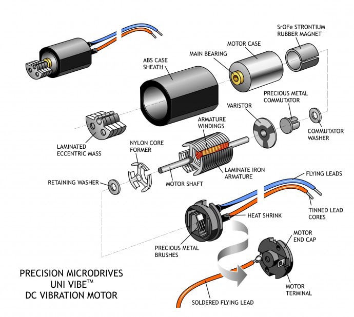
Brushed motors work by applying a current to the armature windings inside the motor. As the windings are inside a magnetic field (produced by the Strontium / Iron magnet shown in the diagram below) the current causes the shaft to rotate. In order for the shaft to continue rotation in the same direction, the current must be periodically reversed as the coils pass through the magnetic field. Without being reversed the shaft would turn only halfway one direction, and then stop.
The current reversal is achieved by precious metal brushes (which remain static) connecting to a commutator on the shaft (which rotates). In the diagram you can see two brushes, the commutator is also made of multiple segments. As the commutator rotates, the current reversal is caused by the brushes connecting to different commutator sections. This action repeats and the motor shaft continues to rotate in one direction.
Drawbacks Of Brushed Vibration Motors
It is these metal brushes that are the main source of failure for motors. They are subject to mechanical wear and particles will eventually fill the gaps between the sections of the commutator, eventually causing a shorting failure. It is also possible that the metal fatigue will come into play and cause the brush to snap, causing an open circuit failure.
In addition, as the commutator rotates and the brushes connect to different sections the motor is liable to what is known as ‘arcing’. Electrical arcs look very similar to sparks but are a continuous discharge instead of the short burst of a spark. This means that they are unsuitable for use in environments with explosive gases as they could cause ignition, and therefore they can’t be ATEX rated.
Arcing can also produce radio interference, though, with additional circuitry/components, this can be suppressed.
How Brushless Vibration Motors Work
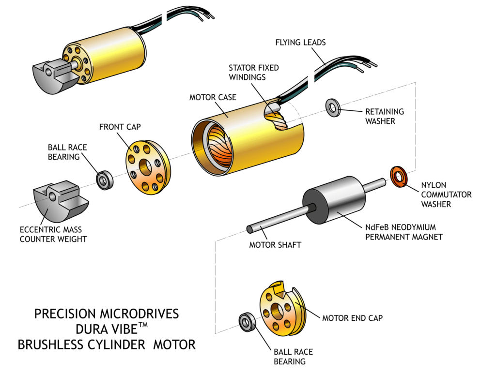
Brushless vibrating motors overcome these issues discussed above by using stationary coils called a stator (as opposed to an armature). Instead of the magnet staying put (as in brushed motors), in the brushless design, the magnet is attached to the shaft and therefore rotates. Power is applied to one coil at a time in a specific pattern. The interaction between the fixed magnetic field, the rotating field of the magnet, and the stationary but varying magnetic field of the windings, causes forces that are translated into the rotation of the shaft.
Now the coils remain stationary, so there is no need for the commutator or the brushes.
This means that brushless vibration motors do not suffer from the same mechanical wear issues as a brushed motor, which translates to a much longer lifespan. This extended operation period makes them ideal for applications that require continuous use, such as some found in the mechanical aid field, or reliable long-service use such as military or industrial tactile alerting.
In addition, the effect of arcing is removed and therefore they are safe to be used in explosive environments and do not interfere with radio signals. This means they can be used in ATEX compliant equipment.
However, this comes at the cost of an extra design requirement. In order for the power to be switched to the correct coil at the right time, the position of the shaft must be determined and signals sent to the correct stator windings. Therefore brushless vibrating motors require an extra control integrated circuit (IC) to ensure their correct operation.
Driving A Brushless Vibration Motor
Some brushless motors have a special driver IC already built inside the chassis, whilst some do not and therefore require external circuitry to drive the motor.
It is usually possible to tell whether there is an integrated driver by the number of connecting leads. Brushless vibration motors that have 3 leads require an external driver, whilst those with 2 leads require simple DC power (+ and -, rated voltage) to drive the internal driver IC.
We will look at how to drive each type in turn.
Brushless Vibration Motors With Integrated Driver
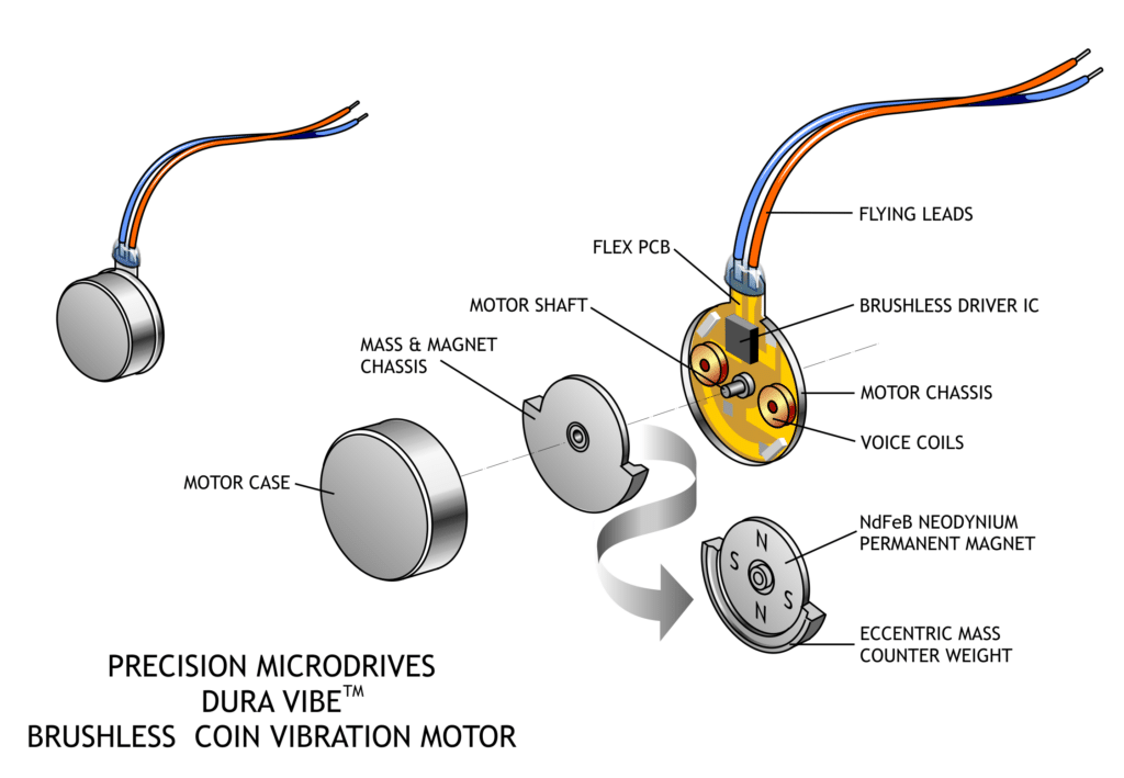
This one is certainly the easier of the two. Simply power the motor with a DC voltage between the lower limit of Certified Start Voltage and the upper limit of the Maximum Operating Voltage to make the motor vibrate. The exploded diagram above is of our 910-10F brushless coin vibration motor and you can see the driver IC besides the connection leads.
It will behave much like a normal brushed vibration motor so there are other topics of electronics that you will want to explore.
- AB-004: Understanding ERM Vibration Motor Characteristics
- AB-005 : Electromagnetic Compatibility (EMC / EMI) with Vibration Motors
- AB-006: Mechanical Mounting for Vibration Motors: to PCBs
- AB-007: Mechanical Mounting for Vibration Motors: to Bulkheads
- AB-009: Securing Vibration Motor Leads and Wires
- AB-010: Mounting Vibration Motors to Flexible Materials & Clothing
- AB-011: Electrical Techniques for Using Different Power Sources
- AB-014: Mechanical Layout of Vibration Motors for Typical User-Interfaces and Controls
- AB-015: Mechanical Mounting for Vibration Motors: Moulded and Machined Enclosures
- AB-016: Experiments in Waterproofing and Overmoulding Vibration Motors
There is one notable difference, however, as the connection leads provide power to the driver IC, it is not possible to use a PWM signal to drive the motors. Instead, this will cause the chip to repeatedly switch on and off, making it unable to correctly measure the motor’s position and drive the shaft effectively.
The other thing to note is that the brushless motor with integrated driver cannot be driven in reverse. Connecting the motor leads back to front (i.e connecting the negative voltage to the red (+) lead and positive voltage to the black (-) lead) will damage the driver IC!
Sensorless Brushless Vibration Motors
Without an internal drive IC, the sensorless brushless vibration motors require some external circuitry to operate the motor. You can construct your own Hall Effect sensor (we’ll be releasing brushless vibration motors with an integrated hall sensor, late 2012) or back EMF measurement circuit, and use a microcontroller to produce the drive signals.
However, due to the low inductance of smaller motors, and therefore low back EMF spikes, it’s difficult to reliably measure back EMF. We struggled to get brushless motor dev kits from Atmel and ST to drive our 912-101 motor correctly, so we turned our attention to the dedicated driver ICs. (It is to ensure compatibility with these driver development kits and as many dedicated driver ICs as possible, that we’re developing a sensor-based version of the 912-101 motor).
Many brushless DC motor driver circuits have sensor and sensorless modes, which will take care of all the position measuring and power control for you. Simply connect the motor to the appropriate pins with the suggested external circuitry.
Based on this approach, we have recommended a driver circuit that we have successfully used with our sensorless brushless vibration motor 912-101.
The DRV11873 And M10-400 Evaluation Board
The easiest way to drive one of our brushless motors is to use the M10-400 Precision Controller™. It is an evaluation board based on the DRV11873 from Texas Instruments, a sensorless BLDC driver chip. It has replaced our previous testing setup of the TDF5140A (below) due to its ease of use and performance.
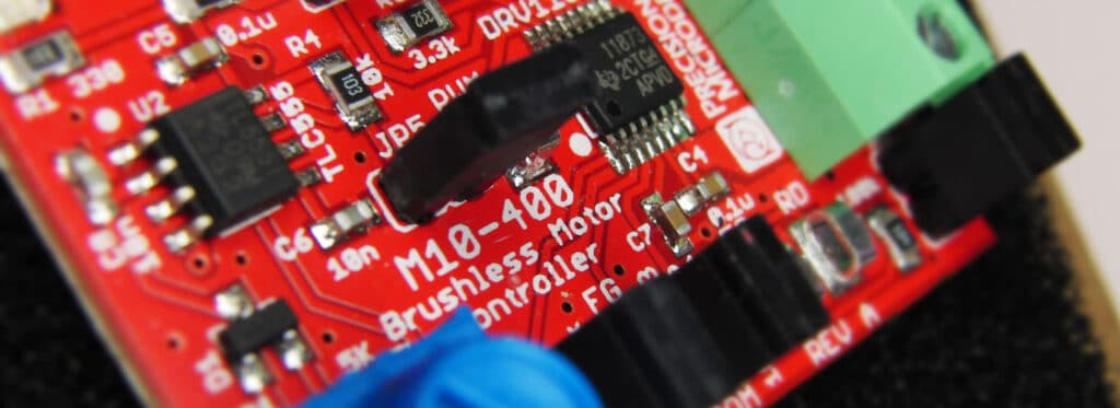
The M10-400 is populated with all the components and circuitry required to drive a delta wound motor with no adjustments, simply connect a 5 V power source and the onboard PWM generator works with the chip to drive the motor. To drive a star wound motor, the resistor network can be removed and the COM port is accessible through the screw terminal. See the discussion on delta wound and star wound motors in the TDF5140A section for more information on this.
For further development, it is possible to connect an external PWM and access all the I/O pins via the SMD test points and jumpers. For more information on the M10-400 and DRV11873, visit the product page to download the datasheet and user guide. The video below shows how easy it is to get up and running with brushless motors:
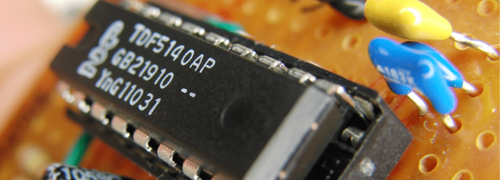
The TDF5140A Sensorless Brushless Vibration Motor Driver Chip
This integrated chip produced by NDX Semiconductors, formerly Philips Semiconductors, is what we previously used to perform our in-house testing of the 912-101. It has a number of major features that have great benefits:
- Full wave commutation (push / pull drivers so the motor shaft is always under force for a smooth rotation)
- Built-in flyback diodes
- A wide range of operating voltages
- Easily controlled by a microcontroller
- Flawless starting (which can be a problem with sensorless brushless motors) with the 912-101
- (Normally) No need for an external sensor circuit
With regards to the last point, we do actually have to make a slight modification to work with the 912-101. Brushless motors come in star or delta (wye) windings. The TDF IC has a built-in back EMF sensor which is based on 4 measuring points, one for each winding and one central point (known as the ‘star point’). However, the 912-101 has a delta winding so we do not have a connection for the central measuring point. Instead, we must simulate the star point from the other connection leads.
The sensor circuit is actually fairly simple. We take each of the motors leads and connect a 110 kOhm resistor in series. All the resistors are then connected together and subsequently connected to MOT0 (pin 17, input from the start point of the motor coils). See the top right section of the circuit diagram below:
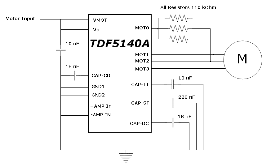
The pins Vp and VMOT are the supply voltage for the chip electronics and the supply voltage for the motor, respectively. We have connected them together to simplify the circuit, however it is also possible to control the electronics and power the motor separately. Vp must be between 4v and 18v, and VMOT must be between 1.7v and 20v. When connected together the minimum applied voltage is therefore 4v.
Download the full datasheet here:
This driver circuit requires the use of a variable analogue DC signal to vary the speed of the motor – this can’t be done with unfiltered PWM.
Conclusion
We have discussed the drawbacks of normal ‘brushed’ vibration motors. These include not being suitable for long service lives and arcing, both due to the internal precious metal brushes. There is another way to construct a DC motor by using stationary windings and a moving magnet. These ‘brushless’ vibration motors are long-lasting and remove the risk of arcing, making them suitable for ATEX compliant equipment.
As a result, they are becoming popular for many different applications, in particular, those that require near-constant operation or are difficult to service.
However, they also require a driver IC that can measure the position of the motor shaft and power the coils accordingly. Some brushless vibration motors already have a driver IC built into the motor casing, like our 910-101 brushless coin vibration motor, but some require an external driver.
An example circuit was shown for the NDX Semiconductor TDF5140A driver IC, which can be used effectively with motors like our 912-101 ERM type brushless vibration motor.
Newsletter
Sign up to receive new blogs, case studies and resources – directly to your inbox.

Sign up
Discover more
Resources and guides
Discover our product application notes, design guides, news and case studies.
Case studies
Explore our collection of case studies, examples of our products in a range of applications.
Precision Microdrives
Whether you need a motor component, or a fully validated and tested complex mechanism – we’re here to help. Find out more about our company.