AB-009
Securing Vibration Motor Leads And Wires
Overview: What Are Linear Resonance Actuators?
Vibration motors require electrical power, which must be delivered by wires or PCB tracks to the motor. Precision Microdrives vibrating motors are available in a range of connector forms. From stock, they are available with factory installed leads, terminals, PCB solder pins, or as PCB SMT / SMD options. Solder pins and SMT motors have the advantage of being mounted directly onto the PCB which simplifies the connection process.
However, both leaded and terminal types will need design consideration to electrically connect them to the driver circuitry. This motor application note covers common problems when using wires (also known as flying leads) with vibration motors, and the best practice solutions.
Since using leads is the most common way of making an electrical connection, this is an important aspect of most of our customer’s designs. A bit of forethought and design work here, can improve product reliability and significantly reduce the number of in-field errors/repair returns.

Get in touch
Speak to a member of our team.
Metal Fatigue Caused By Vibrating Motor Leads
The biggest problem when wires meet vibration is metal fatigue. Nearly all wires have insulation covering the conductor; therefore to make an electrical connection, a short section of insulation must be removed from the wire, so the inner conductor can make the electrical connection.
Often this electrical connection is secured (e.g. soldered to a PCB) and the metal conductor is secured mechanically. If there is vibration present and the insulated part of the wire isn’t also secured, that wire will vibrate and oscillate from the mechanical anchor point. Typically this is between the solder joint and the point where the wire insulation starts. The exposed metal conductor in this area will suffer from fatigue and before long it will snap/break; no more vibration from the motor.
Once this happens, the only fix is to replace or strip and re-attach the wire. Something which in almost all instances will be difficult and costly. The best practice solution, therefore, is to secure the wires, and we cover the options below.
All the solutions revolve around ensuring that the inner conductor and outer insulator parts are held in a rigid line. The insulator will drastically reduce the chances of metal fatigue within the wire between the mechanical joints at either end.
Vibration Motors With Pre-Attached Leads
Before looking at methods for connecting a motor’s power leads at the drive circuit end, lets first look at the best practice for connecting leads to the motor, since they are essentially the same.
Vibration Strain Relief Via Crimps
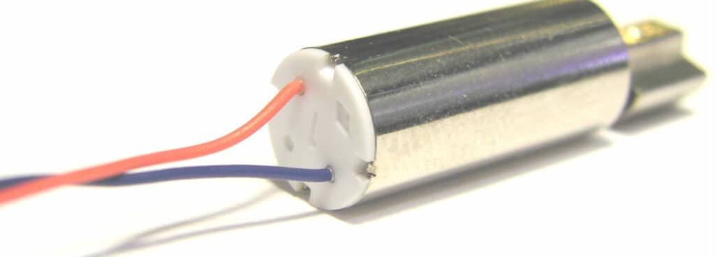
Many motors in the Pico Vibe™ range have AWG 32 leads pre-attached. Strain relief is provided by the motor end-cap, and the connection to the internal commutation circuitry is done via a crimp. The crimp makes the electrical connection and also secures the wire via the insulation. This means that the fatigue point where the insulation is stripped away is no longer a fatigue point because the crimp holds both the stripped and non-stripped part in a fixed place. Therefore there’s much less chance for metal fatigue.
Vibration Strain Relief Via Adhesive
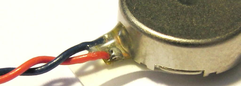
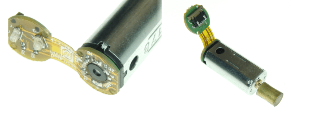
The coin vibration motors are a good example of best practice use of adhesive to secure the leads. Leads are soldered to a flex which sits on the chassis of the coin motor to make the electrical connection. Next, a bead of epoxy is deposited on the point where the wires are soldered to the flex. This bead is large enough to cover the insulation and this removes the strain from the inner conductor between the solder joint and the insulation portion of the wire.
Vibration Strain Relief Via Heatshrink
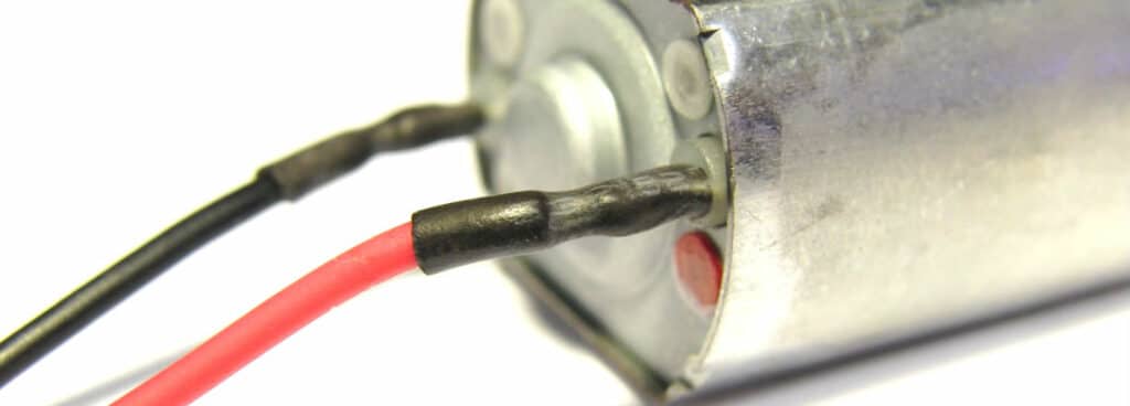
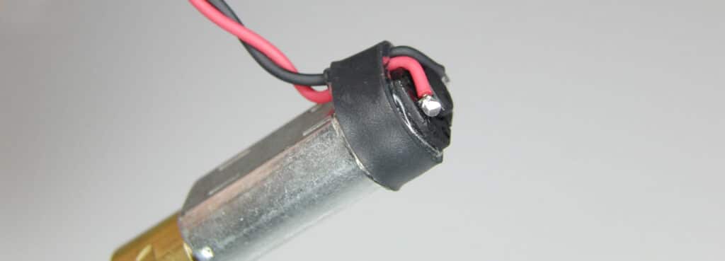
We supply some motors with customised leads. In some cases, we attach leads to motors with terminals, and in these examples, we cover the terminals and a short part of the leads with heatshrink. Heatshrink is a thermo-plastic tube that permanently decreases diameter when heated with a hot air gun. A solder joint makes the electrical connection and the mechanical strain is taken by the heatshrink. We’ve covered a how-to in more detail below.
Adding Wires To Vibration Motors With Terminals
Many of our vibrating motors and most of our Uni Vibe™ range have solder terminals for the customer to connect their own leads. To securely connect leads to our vibration motor terminals, there are two important steps.
The first step is to make a good electrical connection. Our motor terminals are small metal plates with an ‘eye’ in them, similar to a sewing needle. The wire is intended to be stripped to a length such that the insulation runs right up to the terminal, then twined and tinned. The stripped wire should be laid flat against the terminal then soldered together, ensuring the solder has flowed properly and is firmly attached to both wire and terminal. There should be no gaps in the ‘eye’ of the terminal. To improve the soldering process, it may be useful to use some additional flux, which helps spread the solder freely over the terminal and wire.
Secondly, a heat-shrink tubing should be applied over both the terminal and the wire to reinforce the connection. It is important that the tubing cover both the motor terminal and the wire beyond the stripped portion so it also covers part of the insulation. The heat-shrink strengthens the joint by reducing the flexibility of the wire at the point of contact and preventing metal fatigue.
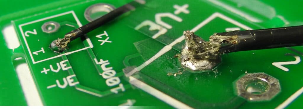
One method to solve the weak part of the joint is to use an adhesive, potting compound or hot-melt to mechanically secure the leads (including a portion of insulation) to the PCB. A strain relief clamp or similar fixing can be used as an alternative, as long as the vibration in the leads does not continue past the clamp to the solder point.
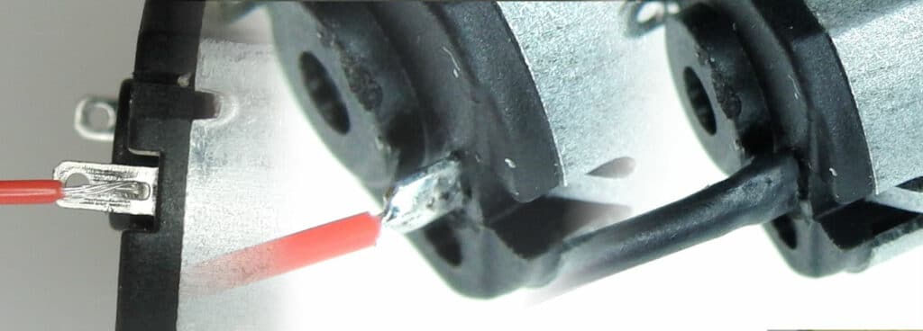
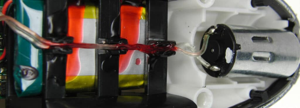
There are of course other methods to the one above. The main aim is to ensure the weakest part of the lead (i.e. the join at the terminals) is not subjected to excess movement. As an example of an alternative method, take a look at the image below. Here a band of self-adhesive heatshrink is used to pin the leads down to the motor casing. When done correctly there is little to no movement of the leads at the terminal. An important factor of this band is the self-adhesive glue, it helps the band stick in place, unlike normal heatshrink bands which can be displaced by vibrations. Another advantage it has over the method above is that the leads are secured at no cost of additional space, unlike the heatshrink above which can add over 1cm to the effective length of the vibration motor.
Adding PCB’s Or Flexible PCBs To Vibration Motors With Terminals
An alternative way to attach wires indirectly to motors is via a PCB that’s soldered to the terminals on the back of the motor. In the photo below you can see an example where a 0.8mm board is soldered to the motor terminals via plated through hole slots.
The flex can then run off to another part of the application, can be terminated in a connector, or wires can be secured to the PCB using the techniques below. Sometimes it’s easier to add these PCBs at time of manufacture, so drop us a line if you think it’s the solution for you.
Soldering Leads To Vibration Motor Drive Circuitry
It’s not just the motor end of the lead that we need to worry about. Vibration will pass along the wire to the other end – the one that is connected to the driver PCB / battery terminal / or whatever the application demands. Therefore this end of the lead needs to be secured correctly as well.
Of course, for some vibration motors, the method for connecting the motor to the drive or power circuit is already dictated by the motor’s design. E.g. motors with through-hole PCB pins such as the 304-100, or motors which use surface mount technology like the 304-109 (since depreciated).
But for those with leads, consider the following best practice methods.
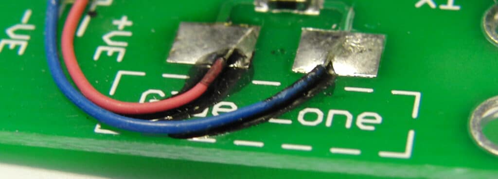
Securing Vibrating Leads To Solder Pads (PCB)
A simple method to make the electrical connection at the driver end is to solder the leads to pads (either thru-hole or SMD) on the PCB. Pads are a simple and cheap method as they do not require any additional components and take up very little room on the PCB. However, they are prone to failure as the wire is only held in place by a mechanical solder joint of the inner conductor.
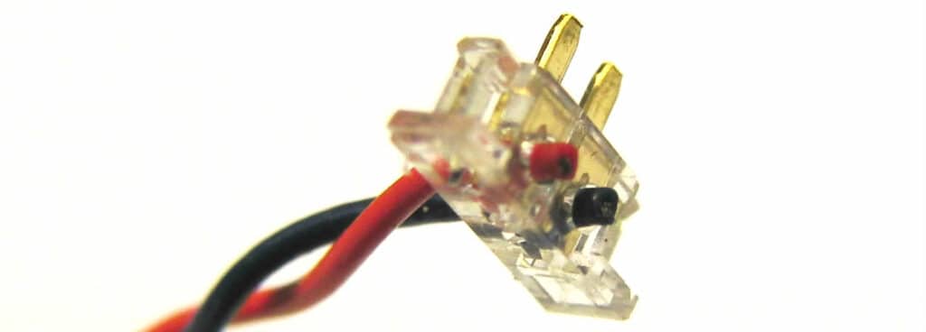
Securing Vibrating Leads To Terminal Pins (Soldered To PCB)
Terminal pins could be an easier way to secure the leads depending on the application. Terminal pins are available for SMD and much more commonly through-hole pads.
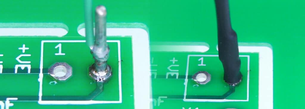
The trick here is to solder the wire to the terminal pin, much like one might do when soldering it to the motor terminal, and then covering the whole thing with heatshrink. Not only does this insulate the terminal pin, but it also proves the necessary mechanical rigidity between the terminal pin and the wire.
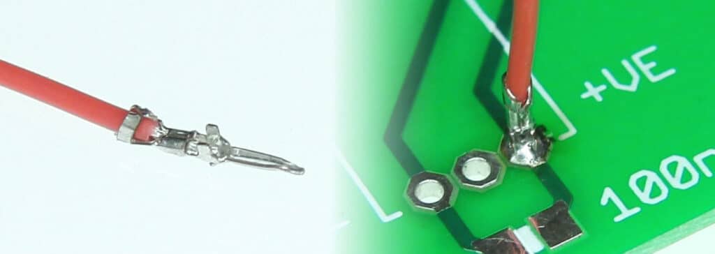
Securing Vibrating Leads Via Male Crimps (Soldered To PCB)
A variant of the terminal pins solution is to find a male crimp that matches the wire-gauge of the lead and then solder the crimp to the SMD pad/through-hole pad. E.g. Molex 50061-8000 male crimps for AWG32 leads of the Pico Vibe Range™. This works because the crimp is designed to provide strain relief and therefore has a rigid portion that keeps the inner conductor and outer insulator rigid.
Vibration Motor Leads And Connectors (Non-Soldered)
Connectors benefit from being more secure than simple solder pads or through-hole soldering because they are designed for strong mechanical rigidity and durable electrical connections. The crimps inside the connector housing hold the motor leads. Of course, connectors are relatively easy to connect and disconnect, which can be particularly useful if the motor will need to be replaced within the lifetime of the product.
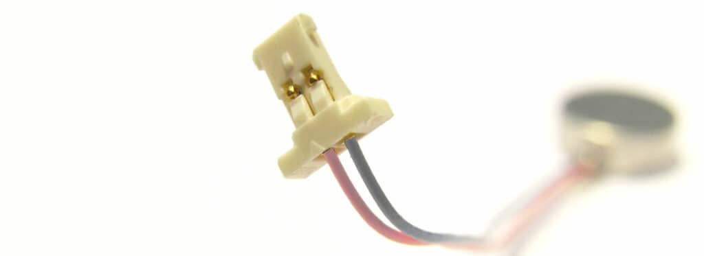
There are broadly two types of wire connectors applicable to the gauges of wire used with vibration motors. They perform the same action in different manners. They both grip the insulation, provide an electrical and mechanical connection, and are shaped to securely fit with a housing counterpart on the PCB. The housing terminals are usually fixed in place with either through-hole soldering or surface mount methods. The terminal and connector hold the lead in place, connecting it to the circuit. This is a common practice in the mobile / cell phone industry, and you can see from our study of best practice vibration motor engineering from the mobility market; often just the motor connector terminals are shown on the schematic.
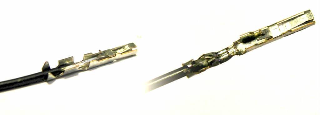
Most connectors are based on crimps, which require a small section at the end of the leads to be stripped. Crimps are formed pieces of metal, with one end shaped to fit into the appropriate connector, and the other end designed to be tightly closed or crimped around the striped wire and insulation. Crimps are ideal for low voltage and low current applications, just like our vibration motors. They are available in a variety of specific designs and quantities and can be applied by hand or machine. It’s a fiddly job to add by hand, so for production runs, it’s best to get us to add them when the motors are made.
An alternative to crimps is insulated displacement connectors or IDCs. Instead of requiring a small strip of insulation removed and then connecting to the exposed wire, IDCs contain blades which cut through the wire and cold-weld themselves to the internal conductor. This makes the process more difficult for small quantities, as the appropriate tools are more expensive than crimping pliers, but can be automated if a large number of connectors are being constructed. These are popular for low voltage and low current applications. Like the crimps, if you’re making more than a handful, consider getting us to do it in our factories.
Lead Sizes And AWG32 Wires
It is important to recognise that when using crimp and displacement connectors that the size of the lead is critical. With vibration present, using the wrong size crimp will often result in a wire coming loose or breaking. Solder pads and through-holes must also be big enough to accommodate the lead if soldering directly to the PCB.
Most of our leaded motors come with AWG32 (American Wire Gauge) sized leads. For a list of commonly available AWG32 compatible connectors, mainly crimps, we have a chart you can download below: AWG32 CRIMPS AND CONNECTORS
It contains a number of connectors and terminals available for AWG32 sized leads, including products from JAE Connectors, JST, and Molex. You can also find the part number for a couple of different distributors. AVX also provide a variety of wire-to-board connectors, mainly IDCs, and you can download their catalogue here: AVX WIRE-TO-BOARD CONNECTORS
We can fit all of these connectors to our motors at the factory if you wish to use them in volume production.
Securing Leads In Applications With Vibration Motors
So having secured both ends of the leads, since these are the areas most prone to failure, let’s briefly turn our attention to what to do with the rest of the leads.
The middle section of the leads can generate noise as they vibrate against each other. To minimise this effect, and aid the connectors’ mechanical enhancements implemented above, the leads should also be secured. This can be achieved by using one, or a combination, of several methods.
Leads should be kept as short as possible and twisted together. Not only will these two points reduce the movement of the leads, but they will also improve EMC performance. Keeping the leads to a minimum length reduces the size of the electrical loop between motor and driver. Twisting paired leads together is common practice for reducing differential mode noise.
In addition to twisting the leads together, heatshrink could be used in the middle of the wire, as well as at either end of the connectors. Whilst this would not have the same improvement on EMC, it would make the wires more rigid and reduce lead oscillation.
Using a glue, potting compound, or clamp to pin the leads to a surface is sometimes an option. It requires a flat surface that is suitable; one that won’t be damaged by the substance or carries signals susceptible to noise, such as a data bus or control signals.
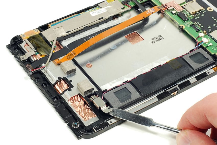
If there is space and the design suits, it may be possible to design a moulded channel for the wires to lie in. Wire ‘raceways’ or conduits are often in consumer electronics when there is a substantial distance between the motor and drive circuitry; the moulded channel keeps the wires neat and prevents them from moving around too much.
Conclusion
Vibration motor leads are more susceptible to metal fatigue than leads that connect other components. This is because the vibration of the motor is often transferred to the leads, and the anchor points where the insulation ends are put under repeated fatigue stress.
Precision Microdrives’ motors that come with leads are supplied ‘secured’ at the motor end. Motors with terminals are designed to have leads connected by the user. It is important that best practice techniques are used to secure these wires to the motor. In addition, leads connected to the drive circuitry are also vulnerable to metal fatigue and need to be secured as part of the design.
We have described the best practice for connecting leads to motor terminals, including solder techniques and heat-shrink tubing. This is followed by a discussion of how to best connect the vibration motor’s leads to the drive circuitry, typically a PCB. There are considerations for solder pads and through-hole connections. Another possible technique is to use connectors, either crimps or insulation displacement connectors. These are widely available from component distributors for prototyping and Precision Microdrives can supply motors with connectors pre-attached.
We’ve finished with some methods to secure the leads within the application. Wires secured at either end are unlikely to fatigue but securing them will help to avoid rattles and other audible ‘irritations’ sometimes associated with the use of vibration within an application.
Newsletter
Sign up to receive new blogs, case studies and resources – directly to your inbox.

Sign up
Discover more
Resources and guides
Discover our product application notes, design guides, news and case studies.
Case studies
Explore our collection of case studies, examples of our products in a range of applications.
Precision Microdrives
Whether you need a motor component, or a fully validated and tested complex mechanism – we’re here to help. Find out more about our company.