AB-014
Mechanical Layout Of Vibration Motors For Typical User-Interfaces And Controls
Overview: What Are Linear Resonance Actuators?
In this Application Bulletin, we will look at the orientation of vibration motors within common user-interfaces and controls, with the aim of producing the best results for haptic feedback or vibration alerting.
First, we consider the importance of understanding vibration forces, before explaining how different motors produce vibrations in different directions (vectors). Example applications are discussed and illustrated to demonstrate the forces that users will experience in different user interfaces.
Vibration Forces Directed Towards The User
The forces produced by vibration motors are actually vectors, they have both a magnitude and a direction. Therefore when designing the mechanical layout of a device, it is important to consider which direction of vibration would produce the best tactile feedback.
The direction which produces the best results for haptic feedback and vibration alerting is almost always towards the user. When the user touches or grips the device, they exert a force on it. The direction of the vibration feedback should be in the same plane as this force, to ensure the full effect of the haptic feedback is felt.
Keeping this in mind, the optimal position of the vibrating motor within the device will depend on the device’s application and how its user or operator interacts with it. For example, a satnav’s touchscreen and a gaming joystick are used in two very different ways, and the placement of the vibration motor will reflect this. In addition, this will also influence the choice of the motor because different motor forms produce vibrations in different directions, as discussed in the following section.

Get in touch
Speak to a member of our team.
Motor catalogue
Looking for our products?
Reliable, cost-effective miniature mechanisms and motors that meet your application demands.
A Motor’s Vibration Direction
Cylindrical Style ERM Vibration Motors

Our most common type of vibration motor is an eccentric rotating mass (ERM) model, sometimes also know as pager motors (since pagers were their first high volume application). These are DC motors with an offset (non-symmetric) mass attached to the shaft. As the motor rotates the eccentric weight, the centripetal forces are unbalanced and this causes a small and rapid displacement of the motor. This repeated displacement is what we know as vibration.
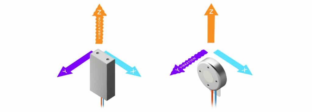
If we look down the shaft of a cylindrical ERM, e.g. 306-101, we can see that the eccentric mass will rotate around the centre of the motor, following a circular path of movement. This means that the motor is vibrating in two directions, along the X-axis and the Z-axis. There is no movement in the Y-axis (which is into the page in the diagram above).
Coin Style ERM Vibration Motors
We also offer a wide range of coin vibration motors which despite their appearance, are also ERMs. See, for example, the 310-103 it works on just the same principle as the cylinder ERM, except it’s smaller and more compact.
In the diagram below, we’ve shown it orientated, such that the vibrator motor’s internal shaft is in the same alignment as the cylindrical ERM above (i.e. in the Y axes), and it therefore also produces vibrations in the X and Z axes. Just bear in mind that coin motors are designed to be mounted/secured on their back surface via an adhesive pad, so in an application, it might not typically be orientated the way we’ve shown (but showing it this way makes it much easier to understand the vibration vectors involved!).

A Quick Tip
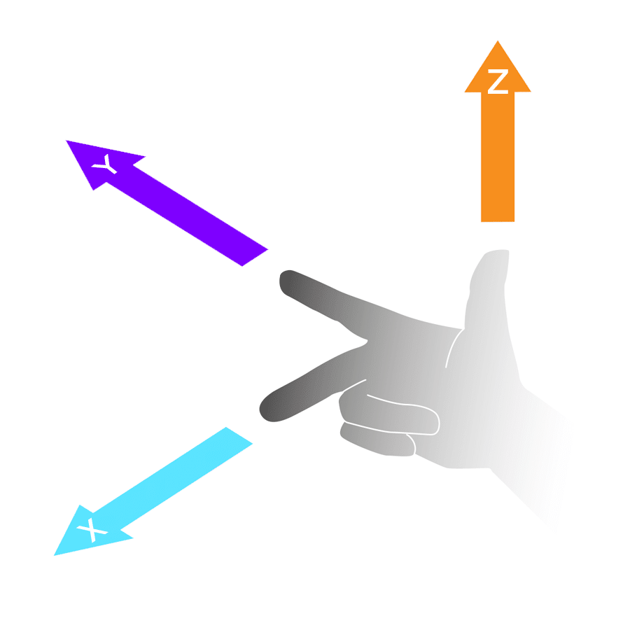
A great method for figuring out the direction of vibration produced by an ERM is to use the ‘right-hand rule’. It is commonly used in physics and maths to help students with the cross product of vectors in 3 dimensions. Variants, such as the left-hand rule and right-hand grip rule, exist for help with magnetic and electromagnetic fields. For ERMs, make a fist with your right hand. Then extend your index finger and thumb fully. Finally, straighten your middle finger so it is a 90° to your index finger. Now, keeping your hand in the same position, if you point your index finger in the same direction as the shaft of the vibration motor there are vibrations present in the direction of your middle finger and thumb. (Ambidexterity enthusiasts will notice this also works with your left hand.)
Linear Resonant Actuators
Linear resonant actuators, such as the C10-100, produce vibrations differently to ERMs. They use a magnet, spring and voice coil to cause motor displacement. The magnet is excited by an electromagnetic field in the voice coil and the spring enables the magnet (which has some mass) to oscillate back and forth around its normal resting position. The magnet is restricted to move in one plane, as you can see above.
Bear in mind that coin LRAs are intended to be mounted on their back like coin ERM vibrating motors. Again we’ve shown the LRA in this plane to demonstrate that it vibrates in a different direction to the two ERM types.
Note also, that some LRAs are configured to produce vibrations in other vectors. The point to take away is that LRAs produce vibration in only one direction.
Finally, it’s worth reminding readers, that due to the LRA’s internal construction, they only work effectively when driven with an AC drive signal at a specified resonance frequency. For more information on driving these vibration motors, see our Application Bulletin 003: How to Drive Linear Resonant Actuators.
Degrees Of Freedom
Before looking at example applications, we should make a quick note about degrees of freedom. ERM motors produce vibrations in two planes. However in some instances, the device they are mounted to only has one degree of freedom, i.e. allows movement in one plane. This means that half the vibration force generated by the ERM motor is dissipated, or in certain circumstances re-vectored into another direction (though in 9 out of 10 cases, the vibration is dissipated within the materials of the application).
A common user interface, especially with tablet PCs and automotive dashboards, is a touchscreen. These are often rectangular and are secured around its perimeter in a rigid housing, usually plastic or metal. This restricts the movement of the screen, where it can only move towards and away from the user due to the flexibility of the material. Any movement in other directions is absorbed by the fixing, re-vectored, or more commonly transferred to other parts of the application where they’ll be dissipated (e.g. the dashboard).
It is worth considering how many degrees of freedom your device has in relation to your chosen vibration motor. In many cases, the vibration strength of the motor is not significant enough to cause damage, but if care is not taken, you’ll start to experience a lot of very annoying rattles and vibration noises which does not make for a good customer/operator user-interface experience.
Example Applications
So now that you know about vibration vectors for a given vibration motor type, and which direction is probably optimal for your application, we can take a look at how best to position/locate vibration motors in various applications. If you are unsure how this relates to your design, please feel free to contact us and our application engineers will happily offer advice on your mechanical layout for your user interface.
Below are examples of how to orientate a vibration motor for different products. In each case, we have suggested the layout to ensure the motor’s vibrational forces are directed towards the user. For your specific design, it may be sufficient to simply make the device vibrate. For example, some user interfaces may be designed to be held in different ways and the system needs to account for all of them; this is the case with mobile phones.
In the examples shown, the coloured arrows show the direction of vibration. In some cases, we have multiple arrows to describe situations that include forces in different directions.
Single Direction Contact
Touchscreen
As mentioned in the above degrees of freedom section, touchscreens are now commonplace. Resistive and capacitive touchscreens are contacted by the user in one direction only when they are pressed. There may be multiple instances simultaneously, for gesture control etc., but all the presses exert pressure in the same direction – into the screen.
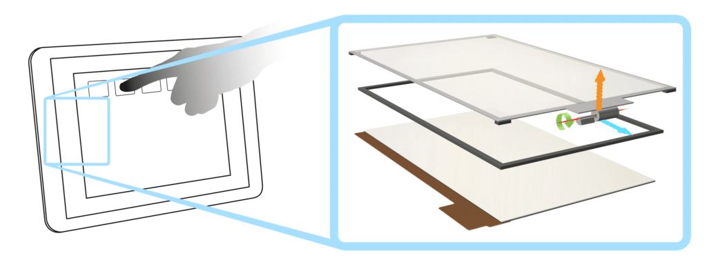
The screen should vibrate in the same plane. This would suggest a cylindrical ERM or an LRA would be best suited for the application as a coin vibration motor would need to be mounted on its side to produce forces in the right direction.
The ideal placement for the vibration motor is right in the middle of the touchscreen. Unfortunately, the touchscreen sits on top of the LCD display so this is not possible. Therefore the motor is usually mounted to the side so it does not interfere with the display.
The display is then ‘floated’ on foam pads that allow it to move slightly and transfer as much of the vibration into the user’s fingers as possible.
Car Dashboard Button Panel
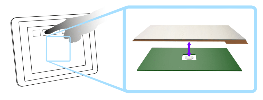
High-end cars are increasingly being fitted with capacitive buttons for normal dashboard functions, such as climate control and the audio system. However, it means that drivers lose the tactile confirmation that comes from traditional mechanical buttons. A solution is to add a vibration motor behind the panel to interact with the user.
It is not practical to vibrate the entire dashboard to confirm a simple button press. Instead, the button panel should be mechanically isolated such that only a small section vibrates. This keeps the size of the motor required small.
Below we have shown how one could mount an LRA to vibrate against the user’s force. This could also be achieved by an ERM, though one might only use an ERM if the panel was on the heavy side.
This can be perfect for LRAs as they produce vibrations in the correct plane, with no extra vibrations transferred to different parts of the system. Also, their small profile and strong self-adhesive pads make them discreet and easy to mount.
Multiple Direction Contact
Joystick
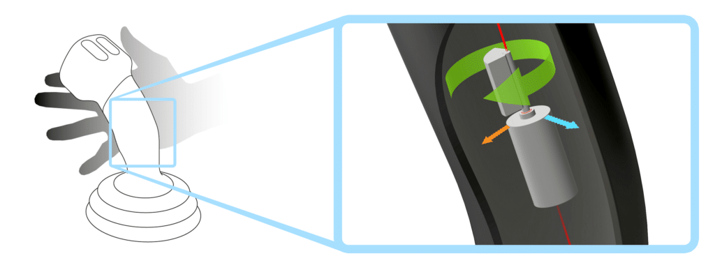
Joysticks are not only popular in gaming but also used for driving vehicles and controlling heavy machinery, such as the crane joystick shown below. When the operator takes a full grasp of the stick, they are only exerting force in two planes.
This is perfect for a cylindrical ERM placed vertically as the vibrations are always in the direction of the user’s grip. A coin vibration motor may also be suitable, if correctly aligned. In fact, this is a similar to our many other devices where the user has a complete grip around a bar. The mechanical layout for adding vibration alerting or haptic feedback to many other handheld or control devices can be analysed in the same manner.
Security Scanner
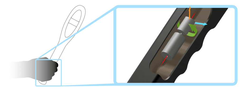
With the joystick example above, the user interface is secured in one position – typically to the machine of a vehicle. However, in lots of cases, the user interface can be the entire device. Consider all handheld applications where the user holds the product in their hand, such as an airport security scanner, now the effective ‘user-interface’ can be held at multiple angles and positions.
However the principle remains the same, that is that the vibration force must be directed towards the typical user grip. From the image below we can observe that regardless of the position the security guard is pointing the security scanner, it is held in the same manner and therefore the position of the vibration motor as remains the same.
Jog Dials And Shuttle Wheels
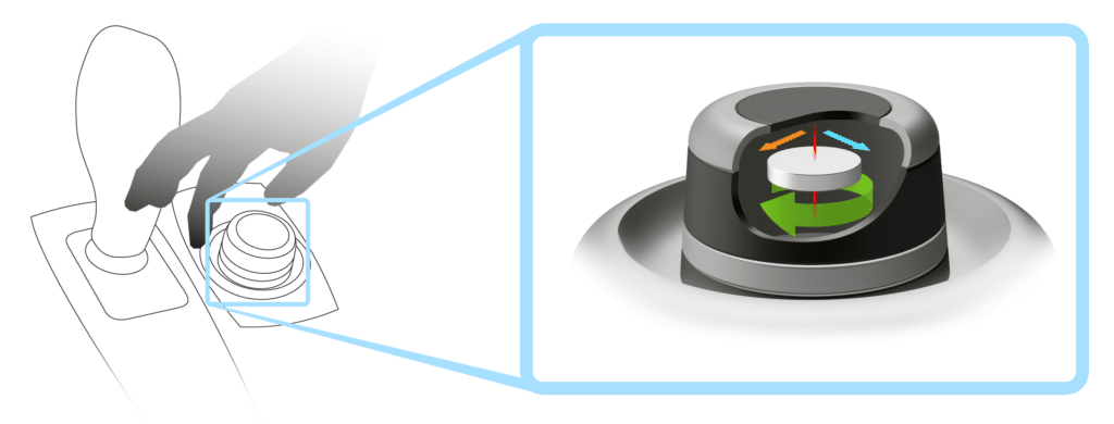
These devices are found in high-end cars and can feature haptic feedback. They are also a common feature on a variety of other products and are often referred to as ‘Jog Dials’ or ‘Shuttle Wheels’. Although the operator only uses the tips of their fingers, similar to the touchscreen example from earlier, the required directions for vibrations are identical to the joystick example.
Therefore the same motor design requirements apply; it is best to use a vertically mounted cylindrical ERM or a horizontal coin vibrating motor. These devices often have a low profile, which may benefit from using a coin vibration motor as they are smaller in height.
Body Worn Vibration Alerting Pack
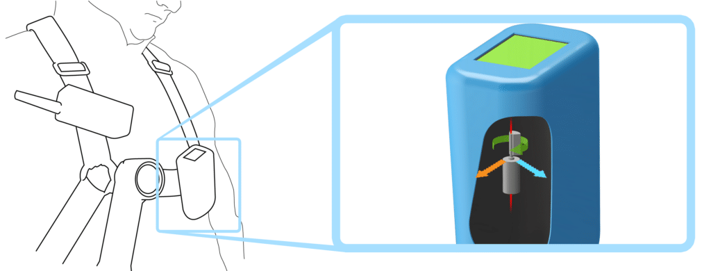
Safety equipment used in hazardous environments can benefit from vibration alerting where the user can be warned of dangers without the requirement for audible or visual indicators. For example, miners can use gas detectors, firemen can be alerted to excessive temperatures, or clean room workers may require such a feature on their air filters.
The pack can be worn in many ways such as belts or backpacks, but we’ve chosen to show a satchel design below. The important consideration is that the vibration motor is positioned so the axes of vibration point into the user. In the satchel example, we’ve demonstrated a vertically mounted cylindrical pager motor (ERM).
Conclusion
To increase a user interface’s vibration performance, it must first be considered how the user interacts with the control unit. Specifically, the direction of the user’s input should be accounted for when considering the type of vibration motor and its mechanical layout.
Ideally, the vibrations from the motor should be in the opposite direction to the user’s input force. ERMs produce vibrations in two planes, whilst LRAs vibrate in one axis only. If the user’s input is in multiple directions, the ERM vibration motor should account for all possible scenarios. With single direction inputs, any vibrations which are not directed at the user will be transferred to other parts of the system. Therefore it is also important to consider the degrees of freedom for the user interface and how vibrations could affect housing and mounts.
We have provided some example applications of typical user interfaces which can easily feature haptic feedback or vibration alerting. In these examples, we show the direction of the user input force and suggest a suitable motor layout to provide the correct vibration forces.
Newsletter
Sign up to receive new blogs, case studies and resources – directly to your inbox.

Sign up
Discover more
Resources and guides
Discover our product application notes, design guides, news and case studies.
Case studies
Explore our collection of case studies, examples of our products in a range of applications.
Precision Microdrives
Whether you need a motor component, or a fully validated and tested complex mechanism – we’re here to help. Find out more about our company.