AB-008
Vibration Motor Best Practices From Mobile / Cell Phones
The mobile phone industry is a huge market in which vibration motors are an established component. Now almost every device has the ability to produce vibration alerts and the field of haptic feedback is rapidly moving forward. In this bulletin we outline some of the common problems cell phone manufacturers face and the electrical best practices to overcome them.
Many of these problems and solutions are applicable to the majority of handheld devices which feature vibration functionality. For those looking to improve an existing product or add a vibration motor to a brand new creation, you may find here, some solutions to problems you have not yet considered, minimise their effects and increase performance.
Voltage Regulation
Problems
When considering how to power a vibration motor within a mobile application, there are two significant obstacles.
First, is likely that the battery voltage is a higher value than the Maximum Operating Voltage of the motor. Running the motor above this maximum value can damage the motor, and cause it to fail prematurely. Therefore a solution is required that reduces the motor’s supply voltage to an adequate level, preferably with high efficiency.
Secondly, the output voltage from a battery will vary depending on its charge. For example, a Li-ion battery that operates at 4.2 V fully charged, may only produce 3.2 V when nearly depleted. If a motor was using the battery as its supply voltage, this would lead to a reduction in performance as the battery drained. It is preferred to provide the motor with a constant supply voltage so that the performance and effects of the vibrations are constant irrespective of charge.

Get in touch
Speak to a member of our team.
Motor catalogue
Looking for our products?
Reliable, cost-effective miniature mechanisms and motors that meet your application demands.
Best Practice Solutions
Thankfully, both problems can be solved using one of three fairly simple solutions. Of these three solutions, using a linear voltage regulator is the most straightforward as it does not impact the motor control circuitry (which is discussed later).
Voltage-regulators typically use a Zener diode in parallel with the load. The Zener diode is a special diode that is designed to operate in the diode’s “breakdown region”, where the voltage drop across the diode is very close to a constant value. The voltage at which the Zener diode enters the breakdown region is known as the breakdown voltage.
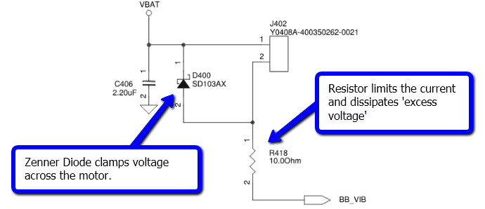
The Zener diode’s breakdown voltage is selected to be equal to the motor nominal drive voltage. The Zener diode will clamp the voltage across the motor with the rest of the voltage appearing across and being dissipated by the resistor.
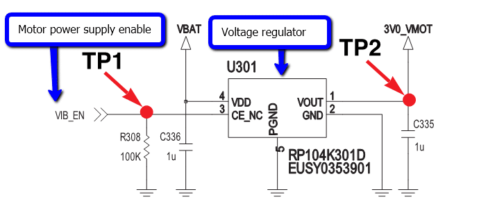
The second alternative is to use an LDO voltage-regulator IC, in which case the input voltage range and output voltage would be clearly marked.
A third solution is to use a motor drive chip which may handle the voltage regulation itself, which will most likely internally use one of the two discrete methods above. Many motor drive ICs can operate at a wide variety of supply voltages, but will not boost the output voltage, i.e. the supply voltage must be greater than the desired output voltage. Obviously, using a motor drive IC will impact upon how the motor is driven.
Electromagnetic Compatibility And Interference (EMC And EMI)
Problems
As a result of motor’s electromechanical operation, they can be sources of electromagnetic interference (EMI). Given that most mobile or cell phones are extremely limited in terms of space, the vibration motor can be in close proximity to very noise sensitive RF circuitry.
Therefore electromagnetic compatibility is a very important consideration. We discuss the subject in detail in Application Bulletin 005: Electromagnetic Compatibility with Vibration Motors.
To summarise the problems discussed in the bulletin, motor’s can generate RF wideband noise through radiated and conduction emissions, and they can also generate high current and voltage spikes which in extreme cases can damage the motor drive circuitry.
Best Practice Resolutions
Decoupling Capacitors
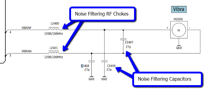
To counteract radiated and conducted noise, decoupling capacitors are commonly used. Placing a ceramic capacitor between the motor’s terminals (as close to the terminals as possible) can remove high-frequency spectra. Often in mobile phones, each motor terminal will also have another capacitor connected to ground to further filter noise. If using a PWM signal (explained in the Motor Control section) to drive the motor, care must be taken to ensure the capacitors filter frequencies above the PWM frequency.
Chokes
In mobile and cell phones the motor is sometimes not located near its drive circuitry. This is often because the motor needs special mechanical considerations when being mounted. For example, you may want to view our Application Bulletins on mounting vibration motors to PCBs or mounting vibrating motors on bulkheads. As the distance between the drive circuitry and motor increases, so does the effect of common-mode current noise. To combat this, many mobile manufacturers use a pair of chokes, which allows differential currents to pass through but has a high impedance for common currents.
Snubbing / Flyback Diodes
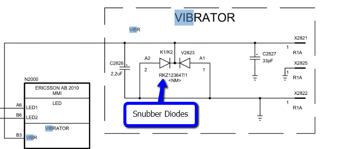
Flyback or snubbing diodes are designed to protect the motor drive circuity from sudden voltage spikes generated by the motor. Either two can be used, one placed at each motor terminal with the anode connected to the ground, or if one terminal is connected to the ground then one can be inserted between the terminals with the anode again connected to the ground terminal. If the motor generates a large voltage spike, the diode enters ‘breakdown operation’ and the spike is safely pushed to the ground.
Motor Control
Considerations
Driving a motor can be very simple or very complex, depending on how much control over the motor is required. For example, if the device was simply to vibrate and switch off when required the circuitry could be relatively straightforward. However for an advanced haptic feedback experience, a haptic driver IC is required. As more devices are becoming touchscreen-enabled, the demand for haptic feedback is ever increasing, however, there is still a market for simpler vibration alerting devices.
The control signal which enables the vibration motor will come from one of the phone’s microcontrollers, but it is not strong enough to drive the motor directly. As such we will look at two common motor drive circuits and then discuss two techniques for advanced motor control.
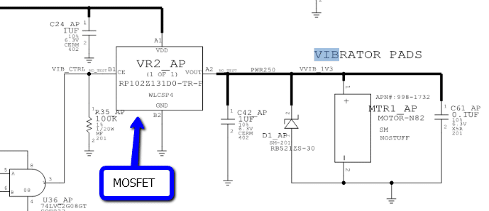
Simple MOSFET Switch (Circuitry)
The basis of the transistor circuit is to provide the motor with power from a high voltage or high current source, whilst using the low voltage and low current signal from the microcontroller to activate the switch. It is possible to do this with either a MOSFET or a BJT, however in mobile applications, the former is preferred. This is because the MOSFET is more efficient (important for battery powered devices) and therefore doesn’t get as hot when operating the motor.
Either P-type or N-type can be used, as the example circuit diagrams above indicate, and are available as discrete chips in a variety of packages. The gate is connected to the microcontroller and dictates wither the MOSFET, and therefore the motor, is turned on or off. For more information, the circuit and peripheral components are discussed in full in Application Bulletin 001 : Discrete Driver Circuits for Vibration Motors.
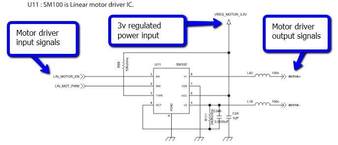
Advanced Motor Drive IC (Circuitry)
One limitation of the simple MOSFET switch, is that it can only drive the motor in one direction.
This may be suitable for a vibration alerting application, but for haptic feedback the motor needs to be easily driven in each direction in order to support ‘reverse braking’. A common technique for controlling motor direction is to use an H-bridge circuit. The operation of H-bridges is well documented, you can read more about them in Application Bulletin 002: Discrete H-Bridge Circuit for Enhanced Vibration Motor Control e.g. Haptic Feedback, and they are commonly available as integrated chips, which use this circuitry in conjunction with advanced control signals. Drive ICs might contain an amplifier instead of the H-bridge which then makes them useful for driving linear resonant actuator (LRA) vibration motors.
Overdrive And Reverse Braking (Control)
Overdrive is the concept of applying a voltage to the vibration motor at a level above the rated voltage for a short period to force it to start quicker. The motor’s supply voltage is then reduced to the normal rated, or desired, voltage for normal operation. This allows for quicker response times by reducing the ‘Typical Lag Time’ and ‘Typical Rise Time’, found in the Typical Haptic Characteristics section of our vibration motor datasheets. Because of the requirement for a second higher voltage connection to the vibration motor, the added complexity to the driver tends to be integrated into a driver IC.
Reverse braking is a technique to stop the motor quickly when it is vibrating. This is done by driving the motor in the opposite direction it’s current rotation, performed by reversing the polarity of the vibration motor’s supply voltage until the motor comes to a rest. The H-bridge circuitry described above enables this sort of motor control and it improves on motor’s the ‘Typical Stop Time’ in the Typical Haptic Characteristics.
PWM Signalling For Haptics (Control)
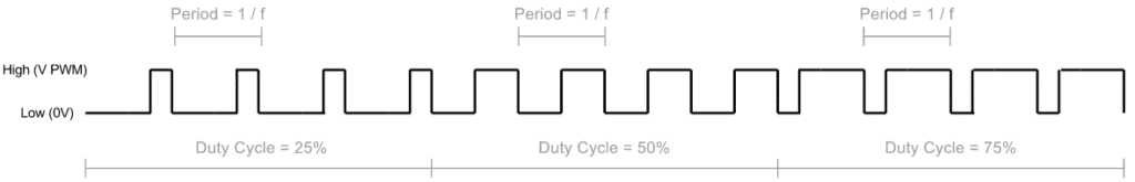
Pulse Width Modulation is a common feature in many microprocessors and often used to control vibration motors in mobile or cell phones. It enables greater control over the motor without altering the voltage level of the supply voltage. A typical circuit would use a PWM signal from the microcontroller connected to the Gate of a MOSFET switch, which in turn is connected to the motor as in the example circuit shown in the section “Simple MOSFET Switch” above. The voltage supplied to the motor () is calculated as follows:𝑉0=𝐷𝑢𝑡𝑦𝐶𝑦𝑐𝑙𝑒𝑡𝑖𝑚𝑒𝑠𝑉𝑑𝑑
Using a PWM is an easy method of implementing the overdrive technique mentioned above. For example, if a motor is rated at 3V and Vdd is set to 4V, a PWM signal with a duty cycle of 75% would provide the motor with a steady 3V. However, a duty cycle of 100% would provide it with 4V, enabling overdrive. Duty cycles below 75% would decrease the vibration strength, and as they are easily programmed within the microcontroller, a variety of vibration patterns can be used and even stored as a library in internal memory or registers.
Many motor drive ICs accept PWM signals as a control input, and some that use H-bridges will support reverse braking, e.g.:
| PWM Duty Cycle | Output |
| 100% | Max. Rotation Clockwise |
| 50% | No Rotation |
| 0% | Max. Rotation Counter-Clockwise |
More information about the available drive techniques will be found in the datasheet or application notes of the chosen motor drive IC.
Conclusion
We have covered with illustrations from real mobile phone schematics, some of the most important electrical considerations for engineers using vibration motors in mobile or cell phones.
These problems and solutions are generally applicable to both vibration alerting and haptic feedback paradigms. Facing problems with voltage regulation, EMC performance, and motor drive circuitry we have also demonstrated the mobility industry’s best practice solutions.
For most issues, there are a number of different solutions available and the final recommendation is left for the reader to decide how best to implement these into their application.
Newsletter
Sign up to receive new blogs, case studies and resources – directly to your inbox.

Sign up
Discover more
Resources and guides
Discover our product application notes, design guides, news and case studies.
Case studies
Explore our collection of case studies, examples of our products in a range of applications.
Precision Microdrives
Whether you need a motor component, or a fully validated and tested complex mechanism – we’re here to help. Find out more about our company.