Adding and improving haptics
Looking for our Haptics range? View our main Haptics hub here.
Overview
Once you’ve evaluated which haptic feedback methods are most appropriate for your application (easily done by using our Haptic Feedback Evaluation Kit), you’ll need to look at implementing the haptic feedback system in your product.
Today’s highly integrated haptics ICs and our open-source software make this a much shorter project with fewer headaches! Below, we give an example of how haptics work at a system level.
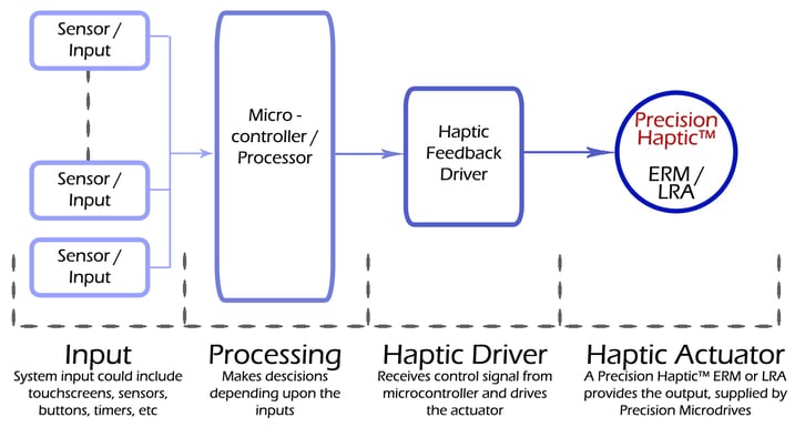
Haptics at a System Level
These elements are considered in greater detail below.
Inputs
In order to transmit information to the user, you must first consider what the haptic feedback or vibration alerts represent. Inputs to the system could be an external physical sensor or switch, like approaching a torque level on an electronic wrench, or an internal trigger like a pre-set time for a clock/watch alarm.
As we discussed in ‘What Makes a Good Haptics Device?’, it is important to consider the type of information you want to relay to your user and how accessible it is. In reality, this is dependent upon the sensors you use as an input to the system. In addition, you’ll need to consider if the inputs need any form of processing before being translated into a haptic effect. For example, turning music into haptic vibrations is a popular example, however, music has several components – mainly pitch and volume. You might decide to represent the volume of bass as vibration strength, which would require some signal processing to filter out frequencies above 200 Hz.
The example above shows how the system is not made from several isolated sections, instead, decisions made in one area influences the choices and constraints in others. We continue with discussing the microprocessor below.

Get in touch
Speak to a member of our team.
Motor catalogue
Looking for our products?
Reliable, cost-effective miniature mechanisms and motors that meet your application demands.
Microprocessor / Controller
Whatever your input, you’ll need a host processor to make alerting decisions and to communicate with the haptic driver.
Previously, the host processor would also have to generate the haptics waveforms and send these via PWM to a driver IC. This would entail complicated license agreements with Immersion (who own most haptics patents).
Thankfully today, cheap and highly integrated haptics processors are available. They contain the actuator driver, libraries of haptics effects and are fully licensed and royalty-free. Our Haptic Feedback Evaluation Kit uses the DRV2605, which can communicate with the processor via I2C, SPI or PWM.
Haptics Processor And Drive Circuit
In general, a haptic driver is required because microcontrollers and processors cannot provide enough current to drive a haptic actuator. This is especially when starting the motor as it needs to overcome the inertia of the mass and the gravitational force – starting the motor quickly is extremely important for high-quality haptics.
To improve the haptic effects, specifically to make the haptic effects more ‘crisp’, two patented techniques are used within haptics processors. The first is ‘overdrive’, where the actuator (motor) is overdriven to reduce the time it takes to reach its nominal vibration level. The second technique is ‘active braking’, where the motor is slowed to rest quicker by applying a reverse voltage until it stops.
Haptics processors automatically handle the electrical signalling when using advanced haptic techniques, such as overdrive and active braking. They can also come with pre-defined haptics libraries – for example, the DRV2605 has a library of over 100 haptic waveforms. This reduces the programming required on the host microcontroller.
The driver may be an external differential amplifier or integrated into a single IC along with a haptics processor like the Texas Instruments DRV2605. You can find out more about this part of the system below.
Haptic Actuator (Precision Haptic™ Range)
The actual vibrations used for haptic feedback are produced by using one of two actuator types.
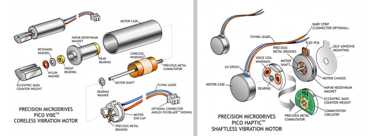
Eccentric Rotating Mass (ERM) Motor
The simpler and less expensive option is the Eccentric Rotating Mass vibration motor or ERM for short. These are available in a cylindrical form, which some refer to as ‘pager motors’, or in a coin form factor.
They work by rotating an unbalanced weight around the motor shaft. The centripetal force causes the motor to displace, and when repeated at it feels like a vibration. As they are built from a normal DC motor, driving them is easy and only requires a DC voltage source that can supply enough current.
They are used extensively for vibration alerting applications, however, they can also be used for haptic feedback when coupled with a suitable processor driver IC. The haptics processor/driver varies the speed of the motor, which in turn affects the vibration amplitude and frequency.
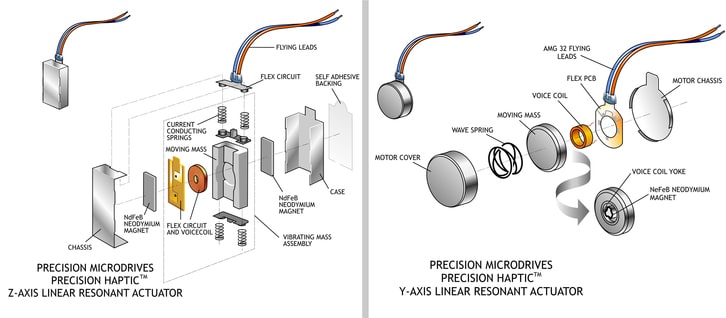
Linear Resonant Actuator (LRA)
Linear resonant actuators are popular in haptic feedback applications because of their low haptic response times and long life.
Built with an internal magnetic mass and spring, an electrical current in the voice coil causes the mass to displace. In order to drive the mass in the opposite direction, the current in the voice coil must be reversed, so LRAs are driven by AC signals. Also, as the mass moves in a straight line, vibrations are only produced on one axis.
They have a couple of advantages over ERMs. They vibrate at a fixed resonant frequency which means that varying the amplitude of vibration doesn’t affect the vibration frequency (which does occur in ERM motors). With no internal brushes or commutators, they have a longer life and also have improved haptic response times.
However, they are limited in vibration strength because they are limited in size. In addition, varying the AC drive signal by a few Hertz will significantly affect the output amplitude because they are effectively a tuned circuit with a high Q factor. Therefore, it is preferable to drive them with an auto-tuning driver – there are several on the market, including the TI DRV2605, which can drive both LRA’s and ERMs.
What Makes A Good Haptics Actuator
Not all haptics actuators are equal. There are a number of different features and specifications that will impact their performance. It is also worth noting that some of the technical differences do not necessarily indicate that one actuator is better than the other, simply that it is different.
The best actuators for haptic feedback can be found in our Precision Haptic™ range. It includes both LRAs and ERMs that have been tested for excellent haptic performance. Many Pico Vibe™, Uni Vibe™, and Dura Vibe™ models are also used in haptic feedback applications, in fact, the 304-103 is one of our most popular SMD motors. So whilst the Precision Haptic™ range may be a great place to start, we strongly encourage you to check out the entire product catalogue or contact our engineers to discuss your application. We introduce our Precision Haptic™ range in the next section.
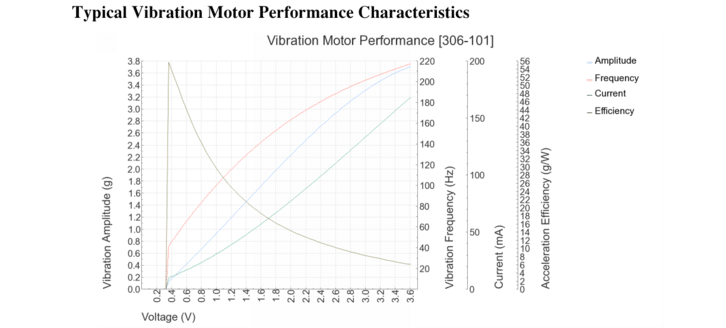
To help you find the perfect vibration motor for your application we produce the most comprehensive datasheets in the industry. Not only do we include specification details (the limits of the unit, e.g. Maximum Operating Current) but we also carefully test and record the characteristics (typical performance values, e.g. Typical Operating Current). One of the most informative sections is the Typical Performance Characteristics Graph which shows how a variety of features vary with the input voltage.
One of the most important sections in our datasheets for haptic feedback applications is the Typical Haptic Characteristics box. For ERMs there are 4 entries, while LRAs have 3. They define how fast (or slow) the motor is, for haptics it is generally preferred to have a quick response. Note that it is possible to improve some of these figures by using techniques such as overdrive, and some driver chips like TI’s DRV2605 (see the last section on this page) will handle active braking automatically.

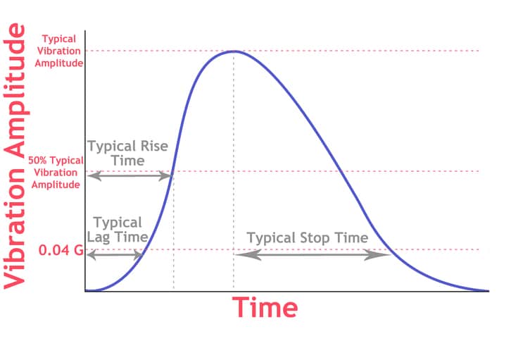
Below is a table that explains each haptic characteristic. The graph shows a vibration motor being driven at its rated voltage to its peak amplitude, then the voltage is set to 0 V and the vibration motor or LRA comes to rest of its own accord.
| Characteristics | Explanation | Notes |
| Typical Lag Time | Time between voltage switched on to vibration amplitude reaching 0.08 G | 0.04 G is the minimum force felt by human skin. Our vibration measurements are peak-to-peak, hence the 0.08 G. The rated voltage of the actuator is used. Can be improved with overdrive. |
| Typical Rise Time | Time between voltage switched on to vibration amplitude reaching 50% maximum G | The rated voltage of the actuator is used. Can be improved with overdrive. |
| Typical Stop Time | Time between maximum G in steady state and vibration amplitude dropping below 0.08 G with no voltage applied | Significantly longer on LRAs as the internal spring stores a lot of energy. Can be improved with active braking. |
| Typical Active Brake Time | Time between maximum G in steady state and vibration amplitude dropping below 0.08 G with reverse polarity Maximum Voltage applied | Not given on LRA datasheets as braking technique is different, although some driver chips support active breaking. Polarity can be switched through H-bridge or certain driver setups. |
The above is a simplified graph to demonstrate the haptic characteristics of a vibration motor. In reality, our test result graphs are more complicated. They combine the input voltage, vibration amplitude (both the measured and peak-to-peak or ‘envelope’), and the current onto the one graph. To aid in understanding the measured haptic characteristics are also presented in an accompanying table. See below for an example Typical Haptic Characteristics graph for a motor in our Precision Haptic™ range:
Introducing The Precision Haptics™ Range
As mentioned above, our Precision Haptic™ range contains actuators that are specially designed for high-end haptic performance. They exhibit the impressive Typical Haptic Characteristics and are tested to the highest level.
The range includes 3 ERMs and 1 LRA. The Precision Haptic™ LRAs are currently available from 1+ quantities through our Product Catalogue. The ERMs are now also released, and available in prototyping quantities just like our LRAs. They cover a range of characteristics and sizes (4 mm, 6 mm, 8 mm, and 10 mm) to help service a variety of different devices.
Digital Playback Engine
The DRV2605 contains a library of pre-configured haptic waveforms and includes a license from Immersion. To use this, you simply select the vibration output you wish to simulate (e.g. long button click) and the driver handles all the actuator signalling for you. There are over 100 different haptic effects pre-loaded.
Alternatively if desired you can still directly drive the actuator from the microcontroller using PWM signalling, or directly with analogue control.
Automatic Overdrive And Active Braking
Fundamental to effective haptic feedback, the driver chip will handle all the electrical techniques we have discussed that increase haptic performance. Overdrive starts the actuator quicker, and similarly, active braking is useful, particularly with LRAs to improve the typical stop time.
Automatic Resonance Detection
This is probably the most useful feature of the driver when using LRAs. As we mentioned before LRAs have a resonant frequency, which the frequency of the AC input signal must match – even a few Hertz off can dramatically reduce performance due to their high Q factor.
Although our LRAs have their rated resonant frequency on their datasheets, it can actually shift due to a number of factors. Elements that can shift the resonant frequency include the mounting surface (flexible vs rigid), temperature, component age (the spring stiffens through its life cycle), and even orientation.
Thankfully chips with automatic resonance detection are able to detect the resonant frequency of the LRA and adjust the signal, ensuring optimal performance throughout the product’s life. This is especially advantageous as many of these influencing factors are out of a designer’s control.
Newsletter
Sign up to receive new blogs, case studies and resources – directly to your inbox.

Sign up
Discover more
Resources and guides
Discover our product application notes, design guides, news and case studies.
Case studies
Explore our collection of case studies, examples of our products in a range of applications.