Encoder Resolution: PPR and CPR
Incremental encoders are used in many different motor applications, where they can provide information on the motor’s speed or the shaft position. Normally, the output signal from an encoder is at least one square wave, but most often it sends two square waves with their phase shifted at 90 degrees – known as quadrature.
For background information on incremental encoders (and how they differ from absolute encoders), you can read our previous blog post, which includes a useful diagram. Encoders have a specific number of pulses per revolution (PPR), which is related to the motor’s mechanical construction. For hall sensor encoders this depends on the number of magnet poles, and for optical encoders, it derives from the number of slots/reflective pads on the interrupter disc.
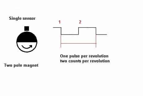
Due to a single sensor being able to use the both signal’s rising edge and falling edge, it is able to provide two counts per revolution of a two-pole magnet – but a total of four counts with quadrature encoders. This ‘count per revolution’ (CPR) is dependent both upon the software and hardware implementation. Be careful to note that some encoder manufacturers use CPR when actually referring to PPR, which may lead to confusion so always double-check the datasheet or with the supplier.
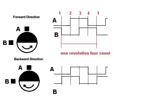
Many microcontrollers have special modules for encoders that enable you to switch to x2 count or x4 count for quadrature encoders: to keep the same level of accuracy in quadrature mode the duty cycle should always equal 50%, otherwise, the resulting accuracy will be less than 4x PPR.
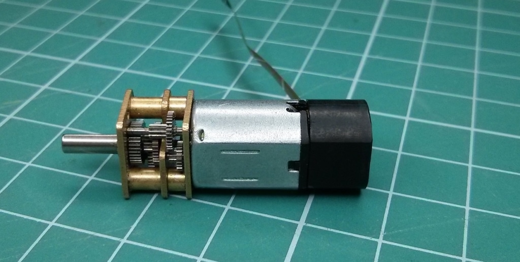
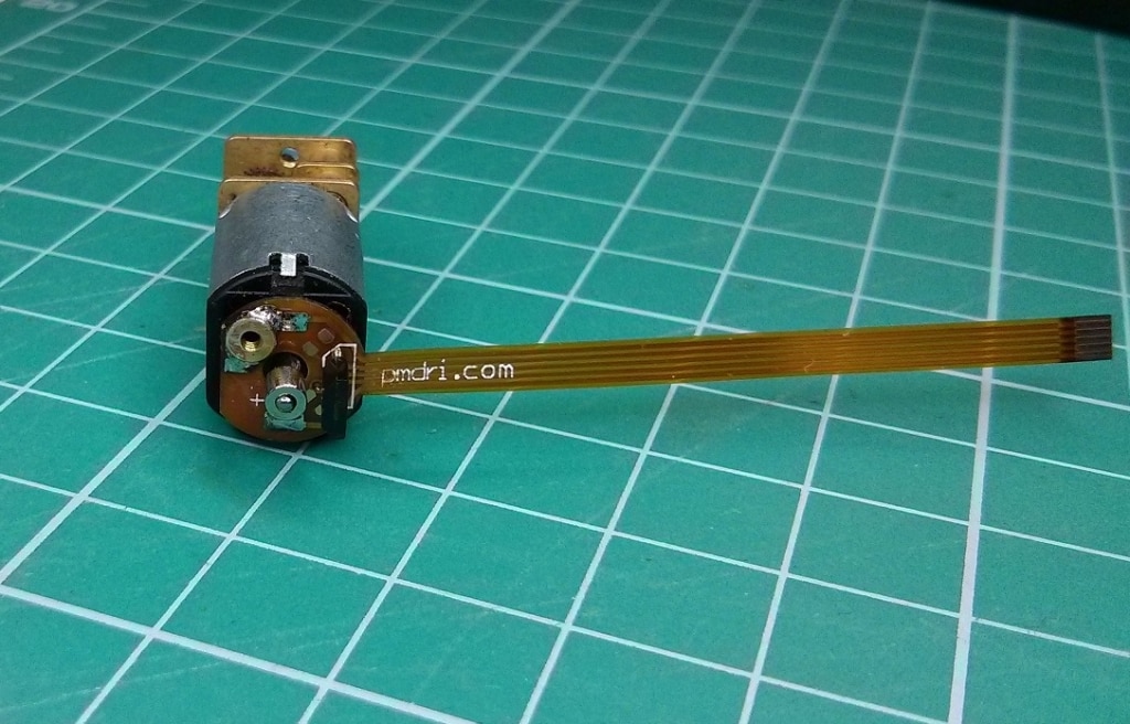
Geared motors like 212-XXX series from Precision Microdrives can be supplied with encoders upon request, where greater positioning resolution on the output shaft is achieved with higher gear ratios. For example, above and below are images of a 212 series motor supplied with a single hall sensor and two-pole magnet. This offers 2 CPR with 29.5:1 gearbox ratio, totalling 59cpr on the output shaft. To increase the CPR using the techniques above, we can simply use an encoder with a quadrature output and a 4 pole magnet. Similarly, we can use one of the 212 gearmotors that features a higher gear ratio, such as the 212-409 which features an impressive high 297.9:1 gearbox.

Get in touch
Speak to a member of our team.
Motor catalogue
Looking for our products?
Reliable, cost-effective miniature mechanisms and motors that meet your application demands.
Newsletter
Sign up to receive new blogs, case studies and resources – directly to your inbox.

Sign up
Discover more
Resources and guides
Discover our product application notes, design guides, news and case studies.
Case studies
Explore our collection of case studies, examples of our products in a range of applications.
Precision Microdrives
Whether you need a motor component, or a fully validated and tested complex mechanism – we’re here to help. Find out more about our company.