Mounting Motors with Glue: Outgassing and Blooming
Introduction
When it comes to mounting motors, a common solution is to use adhesives or glue. Even some of our coin motors and LRAs come with special backings to help keep them in place.
However, these adhesives need to be carefully selected as they can be damaging to the motor, causing reduced performance or even failure. This article serves to highlight some of the potential issues and methods for avoiding them to ensure optimal performance.
What Adhesives are Known to Cause Problems?
The most common culprit that we encounter is cyanoacrylate. You may not be familiar with the term cyanoacrylate but you’ve likely used (or heard of) superglue, which is one common product that it’s used in. It’s also present in a wide variety of other brands of adhesive.
Cyanoacrylate isn’t the only problematic substance, over the years we’ve come across a small number of products that are susceptible to ‘outgassing’ or ‘blooming’. This is where a chemical substance gives off-gas or vapour, which once inside the motor solidifies and sits on the commutator or precious metal brushes.
Adhesives are the most common cause of this problem, often because they are placed on the motor itself and when they are in a liquid state – where most outgassing can occur.
In a recent and more complex example, we saw an RTV silicone adhesive that was holding motors outgas methanol. The methanol then reacted with the spark/arcing that is normally present in a brushed DC motor under load, to create a thin film of acetic acid on commutator and brushes. This, in turn, oxidised the plating on the commutator and brushes leading to high-resistance spots where these components couldn’t conduct properly. As a result, the motors failed prematurely when they came to rest on a non-conductive ‘dead-spot’.
Why We Don’t Provide Definitive Whitelists or Blacklists
Unfortunately, the sheer number of chemicals and materials produced around the world limits our ability to list every product that’s considered either acceptable or unacceptable so far as blooming is concerned. Compiling them all into a single resource, and keeping it up to date, would be no mean feat!
Some applications will use a particular silicon rubber without complaint, while in other situations a seemingly similar product can produce a concerning failure rate. Often this is due to factors other than the glue, such as how air-tight the motor’s body is.
The Typical Effect or Impact
You may be wondering exactly what the effects of blooming or outgassing might look like, and how we identify them in broken motors. The main concern is that material will be deposited on the brushes or the commutator, and thereby inhibit a reliable electrical connection. This can result in reduced performance or even complete failure.
During normal operation of a brushed DC motor, the current will flow to the commutator via the brushes. As the rotor (that is, the moving part of the motor) is continuously rotating the brushes ensure that an electrical connection is made regardless of the rotor position. The brushes are flexible and press against the outside surface of the commutator. When the residue is deposited on the commutator or brush it can prevent the two components from making a full and proper electrical connection. If the build-up of material on the commutator becomes excessive, then the impact on the electrical connection can be so severe that the motor completely ceases to operate.


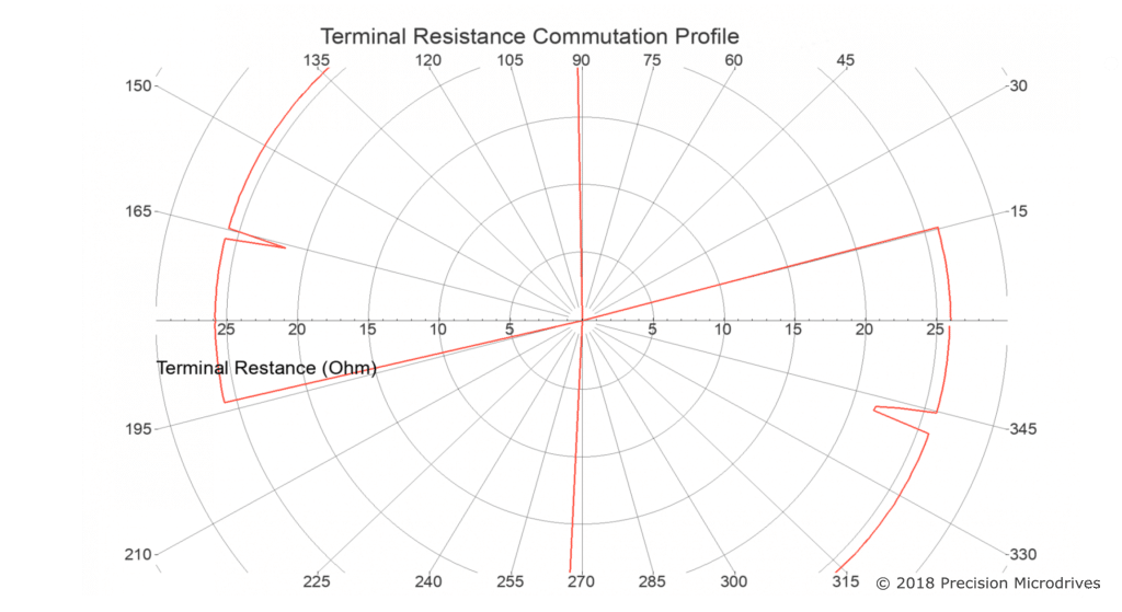
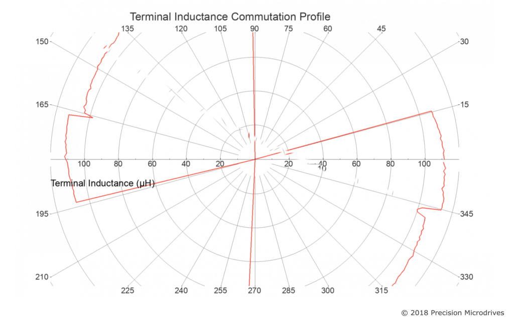
The image above shows how the terminal resistance becomes highly inconsistent when a material is deposited on the brushes and commutator, compared with the ‘clean’ profile in the first image.
In some instances, the resistance can be seen to spike off the chart, at these points the electrical connection (between the commutator and brushes) is so poor that it’s basically an open circuit. If the commutator comes to a stop while the terminal resistance is very high (essentially infinite) then the motor may be unable to start rotating the next time that it is driven. It is only thanks to the momentum that the brushes eventually meet a clean section of the commutator again.
The first images show a clean commutator, with each short gap showing the gaps in the commutator on this 3 pole motor. The consistent reading is a sign of healthy commutator. It’s perhaps worth briefly noting, some brushed motors that use carbon brushes may initially show an erratic terminal resistance, as the brushes create a conductive film on the surface of the commutator. This can usually be remedied by ensuring that the motor is run briefly prior to testing.
In some instances it will be possible to manually motivate a motor, such as tapping or shaking it off a ‘dead-spot’, however performance will then typically be quite unreliable. For non encapsulated or enclosed motors, rotating the motor using an external source (such as using your fingers) can temporarily clean the brushes and commutator.
Brushless motors and LRAs, by virtue of the lack of brushes, are far less susceptible to failure from outgassing. However, that is not to say that are immune to damage from all chemicals, for example, a potent solvent could cause all manner of problems if it comes into direct contact with any of our standard products.
Testing for outgassing problems
Identifying blooming or outgassing as a cause of motor failure can be difficult, in some instances it will be possible to see a white residue with the naked eye, but this is not always the case.
If you suspect that blooming or outgassing is a problem we’re here to help.
In some instances, it can be identified without testing – for example, if a process is changed to include superglue (containing cyanoacrylates) and the failure rate suddenly escalates then it’s likely that the superglue is the issue.
The terminal resistance of a motor can be measured using a multimeter, by connecting to the motor terminals or leads. In the event that there is a prohibitive amount of extraneous material on the commutator then the resistance reading will be very, and/or erratic. However, this test is not conclusive and you may find it difficult to get any sort of reliable reading without professional equipment, such as our in-house test machines. Also, note that it can be difficult, if not effectively impossible, to manually rotate a gear motor with a large reduction.
Even if you’ve taken every reasonable step to exclude potentially suspect chemicals from your assembly process, other processes in the vicinity may use inappropriate chemicals.
One of the techniques that PMD uses to help identify the deposition of extraneous residue is to conduct a commutator profile test – the images above show this output. This method is not definitive, but it certainly helps eliminate various causes.
Every batch of brushed motors and gear motors that we produce is subjected to terminal resistance and inductance profiling across 360°. As such, we continuously improve our own test machines that conduct our ISO9001 controlled testing efficiently and to a very high quality. It systematically moves the rotor and records the terminal resistance and inductance at each point, this then produces a separate polar plot of the resistance and inductance.
An alternative method is to perform a commutator spectroscopy, which can be used in an attempt to identify residue found on commutators or brushes, however, this affects both the time and cost of the investigation.
As always, if you’re struggling to determine whether or not the chemicals used in your assembly are creating outgassing or blooming problems, don’t hesitate to let us know. We can initially offer guidance on how to identify and rectify the issue, and if a more thorough investigation is needed we can certainly assist. We’ve developed considerable expertise and test infrastructure, and our Sales Engineers can guide you through this process.

Get in touch
Speak to a member of our team.
Motor catalogue
Looking for our products?
Reliable, cost-effective miniature mechanisms and motors that meet your application demands.
Newsletter
Sign up to receive new blogs, case studies and resources – directly to your inbox.

Sign up
Discover more
Resources and guides
Discover our product application notes, design guides, news and case studies.
Case studies
Explore our collection of case studies, examples of our products in a range of applications.
Precision Microdrives
Whether you need a motor component, or a fully validated and tested complex mechanism – we’re here to help. Find out more about our company.