AB-027
Eccentric Mass Parameters For Vibration Motors
Overview
When modelling the response of a system containing an eccentric rotating mass (ERM) vibratory motor, it is important to know the weight of the rotating mass as well as it’s eccentricity (that is the offset of the centre of mass of the weight, as measured from the centre of the shaft). There are various methods of modelling such systems and most, if not all, will require this information. Knowing the eccentricity enables you to calculate the vibration amplitude at a given frequency, or calculate the additional torque loading due to gravity.
Imagine an object hanging freely from a piece of string, the centre of gravity (centroid) will always sit directly below the string that supports it. If we were to hang the same object various times in different positions, recording the position of the object in relation to the string each time, we would be able to calculate the position of the centroid for the object. This method, while simple to carry out, is prone to error and most suited to large and complicated objects.
The modelling of Linear Resonant Actuators (LRAs) is not concerned with the eccentricity as they do not generate vibration through rotational movement, but rather a periodic oscillation along a single axis. Therefore, this post only considers ERM actuators.

Get in touch
Speak to a member of our team.
Motor catalogue
Looking for our products?
Reliable, cost-effective miniature mechanisms and motors that meet your application demands.
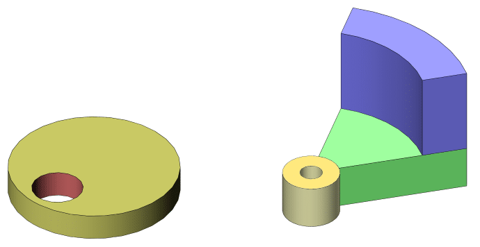
Typically we see two different types of eccentric masses on ERMs:
- Offset Disc – Simply a cylinder with a hole for the shaft, which is offset from the centre of the disc. This creates an eccentricity which in turn produces the vibration when rotating about the shaft.
- Disc Segment – A circular segment, imagine the shape of a slice of pizza. They are often flat with uniform thickness, but this is not always the case. Some variants are thicker near the outer edge (shown in blue in the above diagram). Returning to our delicious pizza slice, imagine the pizza maker has made the crust very high, far higher than the rest of the pizza. With this type of mass, we can achieve a different dynamic and increase the amplitude of the motor without increasing the overall size.
There are a number of modifications that can be made to these shapes, such as adding chamfers and fillets, mounting holes, weight reduction near the shaft, and more. In the following calculations, we omit these details and use simplified models.
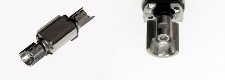
The 304-011 Pico Vibe™ 4mm vibration motor (since depreciated) is an excellent example of how a disc segment ERM can be manufactured with a number of modifications, despite a radius of only 1.7mm! Note how there is more material at the outer edge of the weight, this serves to increase the vibration amplitude with a minimal increase in overall weight.
Masses can be cast, injection moulded, machined or pieced together from multiple plates, and are often made out of tungsten carbide because of its exceptionally high density (15.63 g/cm³). This enables us to make vibration motors with a high amplitude in a small form factor. The densest naturally occurring element is osmium, with a specific gravity of 22.6 g/cm³! But unfortunately, it is very brittle in its natural state.
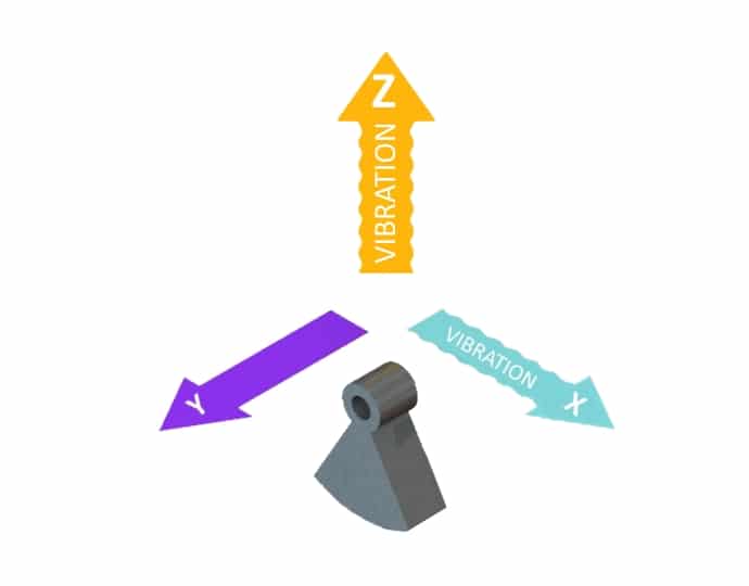
The models we will be looking at cause vibration in the X and Z directions (see the image below) and as such we are not concerned with the offset in the Y direction. In the XZ plane both of the weights are symmetric across the X-axis, so we can also ignore the Z offset. However, we will need still need to calculate the total volume if the height is not consistent across the ERM.
Note, if a mass has uniform height we can view it as a 2D item and use the calculated area rather than volume.
- Declare an origin
In both of the following examples, we will use the centre of the shaft (as viewed from above) as our origin.
- Identify basic shapes that the weight is comprised of, such as rectangles, circles and circular segments
With the offset disc, there are only two circles/cylinders, one for the exterior perimeter of the weight and another for the shaft. The partial disc is slightly more complicated, especially if you have the raised outermost section (C).
- Calculate their individual centroids and volume (or area)
- Combine the values and divide by the total volume (or area)
- Calculate overall centroid
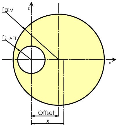
Definitions Used (see diagrams below)
𝑟𝑆𝐻𝐴𝐹𝑇 : radius of the shaft hole.
𝑟𝐸𝑅𝑀 : outside radius of the mass itself.
𝑂𝑓𝑓𝑠𝑒𝑡 : distance from the geometric centre of the mass to the origin.
𝐻𝑒𝑖𝑔ℎ𝑡 : height of the segment of the mass when viewed in cross-section.
𝐴𝑛𝑔𝑙𝑒 : the angle of the segment, important for disc segment masses.
Offset Disc
To ease into the calculations we will initially find the centroid of an offset disc. Remember how we decided to exclude chamfers and other similar features? Well, that now makes our lives a lot easier as we can view the ERM as a 2D object, and simply calculate the area rather than the volume.
Both the area of the outside footprint and the shaft are calculated individually using the same simple formula:𝐴𝑟𝑒𝑎=𝜋𝑟2𝑇𝑜𝑡𝑎𝑙𝑚𝑎𝑠𝑠𝐴𝑟𝑒𝑎=𝜋𝑟2𝑚𝑎𝑠𝑠–𝜋𝑟2𝑆𝐻𝐴𝐹𝑇=𝜋(𝑟2𝑚𝑎𝑠𝑠–𝑟2𝑆𝐻𝐴𝐹𝑇)
Should we later wish to calculate the weight of the mass we would first need to calculate the volume of the mass, this is achieved with the following formula:𝑉𝑜𝑙𝑢𝑚𝑒=𝑇𝑜𝑡𝑎𝑙𝑚𝑎𝑠𝑠𝐴𝑟𝑒𝑎×𝐻𝑒𝑖𝑔ℎ𝑡
The centre of mass of a compound object can be calculated if we know the characteristics of the constituent objects. Consider a compound object which is comprised of two known constituent objects. The centroid is given by;𝑥¯=(𝐴𝑟𝑒𝑎2×𝑥¯2)–(𝐴𝑟𝑒𝑎1×𝑥¯1)𝐴𝑟𝑒𝑎2–𝐴𝑟𝑒𝑎1
The position of the centroid for an offset disc is hence defined by the following equation:𝑥¯=(𝑂𝑢𝑡𝑠𝑖𝑑𝑒𝐴𝑟𝑒𝑎×𝑂𝑓𝑓𝑠𝑒𝑡)–(𝑆ℎ𝑎𝑓𝑡𝐴𝑟𝑒𝑎×0)𝑇𝑜𝑡𝑎𝑙𝐴𝑟𝑒𝑎𝑜𝑓𝑚𝑎𝑠𝑠𝑥¯=(𝜋𝑟2𝑚𝑎𝑠𝑠×𝑂𝑓𝑓𝑠𝑒𝑡)–(𝜋𝑟2𝑆𝐻𝐴𝐹𝑇×0)(𝜋𝑟2𝑚𝑎𝑠𝑠–𝜋𝑟2𝑆𝐻𝐴𝐹𝑇)
Simplifying further we have:𝑥¯=(𝜋𝑟2𝑚𝑎𝑠𝑠×𝑂𝑓𝑓𝑠𝑒𝑡)𝜋(𝑟2𝑚𝑎𝑠𝑠−𝑟2𝑆𝐻𝐴𝐹𝑇)
Disc Segment
Lets now calculate the centroid for a disc segment mass. While we could calculate the centroid with one single formula, for the purpose of clarity we will instead calculate the centroid and volume of each constituent shape rather than solving it all at once.
Reducing the overall mass to a number of different shapes we see:
- The inner shaft collar, a simple cylinder with a hole for our shaft.
- The main wedge, this is the eccentric mass that is typically causing the majority of our vibration.
- Edge protrusion, this section is not always used but can be used to increase the force of vibration without a large increase in overall mass or outside dimensions.
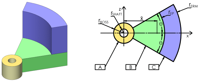
Note that θ is not the angle of our disc segment, but rather half the angle of the disc segment.
Centroid For A Cylinder
The centroid for a cylinder, or a cylinder with a concentric hole, is in the middle.𝑥¯𝐴=0
The area is calculated using the following formula.𝐴𝑟𝑒𝑎𝐴=𝜋𝑟2𝐵𝑂𝑆𝑆–𝜋𝑟2𝑆𝐻𝐴𝐹𝑇=𝜋(𝑟2𝐵𝑂𝑆𝑆–𝑟2𝑆𝐻𝐴𝐹𝑇)
Centroid For Sector Of A Circle
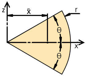
We can calculate the centroid (x̄) of a symmetric circular segment using this simple formula:𝑥¯=2𝑟𝑠𝑖𝑛𝜃3𝜃
The area of this shape is also very easy to calculate:𝐴𝑟𝑒𝑎=𝜃𝑟2
However, to calculate the centroid of either segment B or C we need to use a slightly more complicated formula, as we must subtract the smaller area from the two sections. Although the individual segments may vary in height, each one is itself uniform. As such we can use the area, as opposed to the volume, to calculate the centroid for each segment.
The area is calculated using this formula:𝐴𝑟𝑒𝑎𝐵=𝜃𝑟2𝑚𝑎𝑠𝑠–𝜃𝑟2𝐵𝑂𝑆𝑆=𝜃(𝑟2𝑚𝑎𝑠𝑠–𝑟2𝐵𝑂𝑆𝑆)
The centroid is calculated with the following:𝑥¯𝐵=(𝜃𝑟2𝑚𝑎𝑠𝑠×2𝑟𝑚𝑎𝑠𝑠𝑠𝑖𝑛𝜃3𝜃)–(𝜃𝑟2𝐵𝑂𝑆𝑆×2𝑟𝐵𝑂𝑆𝑆𝑠𝑖𝑛𝜃3𝜃)𝜃𝑟2𝑚𝑎𝑠𝑠–𝜃𝑟2𝐵𝑂𝑆𝑆
Again, simplifying we have:𝑥¯𝐵=2𝑠𝑖𝑛𝜃(𝑟3𝑚𝑎𝑠𝑠–𝑟3𝐵𝑂𝑆𝑆)3𝜃(𝑟2𝑚𝑎𝑠𝑠−𝑟2𝐵𝑂𝑆𝑆)
The centroid for section C is calculated in the same fashion, however we use 𝑟𝐸𝑃 in place of 𝑟𝐵𝑂𝑆𝑆.
As the three segments may not necessarily be the same height we will calculate the volume, and hence the relative weight, of each segment.
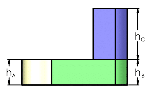
𝑉𝑜𝑙𝑢𝑚𝑒=𝐴𝑟𝑒𝑎×𝐻𝑒𝑖𝑔ℎ𝑡𝑉𝑜𝑙𝑢𝑚𝑒=𝜃𝑟2×ℎ𝑉𝐴=𝐴𝑟𝑒𝑎𝐴×ℎ𝐴
Now that we have the volume and centroid of all three individual segments we can combine them to find the total volume of the mass, as well as its centroid.𝑥¯=(𝑉𝐴×𝑥¯𝐴)+(𝑉𝐵×𝑥¯𝐵)+(𝑉𝐶×𝑥¯𝐶)𝑉𝐴+𝑉𝐵+𝑉𝐶
As 𝑥¯𝐴 is equal to zero we can simplify this further.𝑥¯=(𝑉𝐵×𝑥¯𝐵)+(𝑉𝐶×𝑥¯𝐶)𝑉𝐴+𝑉𝐵+𝑉𝐶
If we were using a mass that had no edge protrusion and the height was constant then we could ignore the volume and use the area calculated above.𝑥¯=(𝐴𝑟𝑒𝑎𝐴×𝑥¯𝐴)+(𝐴𝑟𝑒𝑎𝐵×𝑥¯𝐵)𝐴𝑟𝑒𝑎𝐴+𝐴𝑟𝑒𝑎𝐵
Once again simplifying we would have the following.𝑥¯=𝐴𝑟𝑒𝑎𝐵×𝑥¯𝐵𝐴𝑟𝑒𝑎𝐴+𝐴𝑟𝑒𝑎𝐵
Calculating Mass Weight
Once we know the total volume of the mass and the density of the material we can very easily calculate the total weight.
Remember, density is frequently specified as g/cm³ or kg/m³ so confirm your volume is in the correct units.𝑊𝑒𝑖𝑔ℎ𝑡=𝑉𝑜𝑙𝑢𝑚𝑒×𝐷𝑒𝑛𝑠𝑖𝑡𝑦
Real World Calculation
Let’s now use what we’ve learnt to calculate the centroid location and weight of a given ERM. We will use the Uni Vibe™ 308-103, as it’s a near-perfect example of a brass offset disc ERM. The astute reader may note that our model does not fully capture all of its details, as it has a small chamfer on each end. Assuming that the ERM is perfectly round and the chamfer is consistent around the mass we will find that it actually has no influence on the location of the centroid. The effect on the overall weight will be minimal, so for the purposes of this example, we will ignore it.
Let’s first define all the relevant parameters that we know.
𝑟𝐸𝑅𝑀=4.25𝑚𝑚𝑟𝑆𝐻𝐴𝐹𝑇=0.5𝑚𝑚𝑂𝑓𝑓𝑠𝑒𝑡=2.75𝑚𝑚𝐻𝑒𝑖𝑔ℎ𝑡=8𝑚𝑚𝐷𝑒𝑛𝑠𝑖𝑡𝑦=8.5𝑔/𝑐𝑚3𝑇𝑜𝑡𝑎𝑙𝑚𝑎𝑠𝑠𝐴𝑟𝑒𝑎=𝜋(𝑟2𝑚𝑎𝑠𝑠–𝑟2𝑆𝐻𝐴𝐹𝑇)𝑇𝑜𝑡𝑎𝑙𝑚𝑎𝑠𝑠𝐴𝑟𝑒𝑎=𝜋(4.252–0.52)=55.96𝑚𝑚𝑥¯=(𝜋𝑟2𝑚𝑎𝑠𝑠×𝑂𝑓𝑓𝑠𝑒𝑡)𝜋(𝑟2𝑚𝑎𝑠𝑠−𝑟2𝑆𝐻𝐴𝐹𝑇)𝑥¯=(𝜋4.252×2.75)𝜋(4.252−0.52)𝑥¯=156.0555.96=2.79𝑚𝑚𝑉𝑜𝑙𝑢𝑚𝑒=𝐴𝑟𝑒𝑎×𝐻𝑒𝑖𝑔ℎ𝑡=55.96×8=447.68𝑚𝑚3𝑊𝑒𝑖𝑔ℎ𝑡=𝑉𝑜𝑙𝑢𝑚𝑒×𝐷𝑒𝑛𝑠𝑖𝑡𝑦𝑊𝑒𝑖𝑔ℎ𝑡=447.68×8.51000≈3.8𝑔𝑟𝑎𝑚𝑠
Conclusion
There we have it, some basic techniques for figuring out the weight of your mass, and where its centre of gravity lies.
We’ve included the working for using basic offset disks and complicated disk segments. For each, the centroid of the overall mass is calculated by considering the mass as several smaller parts.
At Precision Microdrives we are able to help with custom weight designs for use with our motors, if you would like more information or to discuss this with our engineering team then please contact us with your requirements!
Newsletter
Sign up to receive new blogs, case studies and resources – directly to your inbox.

Sign up
Discover more
Resources and guides
Discover our product application notes, design guides, news and case studies.
Case studies
Explore our collection of case studies, examples of our products in a range of applications.
Precision Microdrives
Whether you need a motor component, or a fully validated and tested complex mechanism – we’re here to help. Find out more about our company.