5 Methods of Circuit Protection for Gearmotors Part 1
Note: this is the first of two parts looking at limiting current for gearmotors, our next post will complete the article.
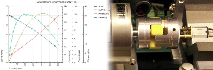
Our gearmotors are frequently used to drive a variety of industrial mechanisms, such as linear actuators or pulleys. A common design consideration in such applications is circuit protection of the motors.
If an actuator reaches its mechanical limit or there is a fault with the mechanism, the gearmotor will keep on trying to turn even if it can’t. In a “stall” condition such as this, the motor draws a lot of current from the power source, which is potentially damaging to the motor coils due to overheating.
The solution? Include some protective circuitry to monitor the current to the motor, and prevent prolonged high currents from damaging the motor. On our product datasheets, you will find the Maximum Operating Current and Maximum Start Current listed under the Operational Specification section. We will use the former as a guide for the maximum current permissible for continued use, and the latter as a guide for the maximum current that is permitted over short periods of time.
Use a Hall Effect to Voltage IC
One way of monitoring the current draw is by using an integrated circuit that uses a hall effect sensor to measure the current through a wire. Such ICs output a voltage that is proportional to the current, which can be measured with a microcontroller, which in turn can adjust the motor supply voltage, and thus reduce the current drawn by the motor. One such IC is the ACS712 from Allegro MicroSystems, for which there is a breakout board available. By including and adjusting an op-amp gain stage after the sensor, the user can select the precision of the current measurement.
The Hall effect is a physical phenomenon whereby a voltage gradient is produced across a current carrying conductor in a direction perpendicular to the direction of the current when the conductor is placed in a magnetic field. This is a useful phenomenon for current measurements because the wires carrying current (in our case to the motor) will produce a magnetic field, which a Hall effect sensor can measure without altering.
However, care should be taken if using a hall effect sensor, as it is an indirect measurement of the current. Stray magnetic fields can affect the reading, and therefore and subsequent decision-making by a microcontroller based on this measurement may also be affected. To find out just how susceptible the ACS712 and ACS713 are to stray magnetic fields, please consult the manufacturer’s website.
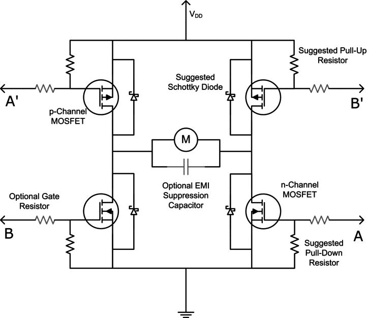
Use an H-bridge IC with Load Current Feedback
As covered in a previous post, H-bridge controllers are useful for advanced haptic feedback. Some H-bridge controllers can be used not only to drive the motors but also to help protect them, such as the Freescale Semiconductor MC33887. This controller includes a load current feedback feature, which provides a proportional current output ( ∝ 1/375th of the load current in real-time from its “FB” pin). By placing an external resistor between the feedback pin and ground the current can be converted into a proportional feedback voltage, suitable for measurement with a microcontroller’s ADC.
Ensure you choose a resistance value according to 100Ω<R<200Ω for linear operation.
That’s it for part one, in our next post we’ll review using a current shunt monitor and a transistor-based method using a few discrete components!

Get in touch
Speak to a member of our team.
Motor catalogue
Looking for our products?
Reliable, cost-effective miniature mechanisms and motors that meet your application demands.
Newsletter
Sign up to receive new blogs, case studies and resources – directly to your inbox.

Sign up
Discover more
Resources and guides
Discover our product application notes, design guides, news and case studies.
Case studies
Explore our collection of case studies, examples of our products in a range of applications.
Precision Microdrives
Whether you need a motor component, or a fully validated and tested complex mechanism – we’re here to help. Find out more about our company.