5 Methods of Circuit Protection for Gearmotors Part 2
Note: this is the second of two posts, continuing on from this post.
Use a Current Shunt Monitor
Current shunt monitoring takes two forms – high side and low side current sensing. Each has its own advantages/disadvantages and each is available as an analogue or digital output device. Current shunt monitor ICs work by carefully monitoring the voltage drop over a low-value resistor that is placed in the current path. An example of such a monitor is the INA170.
Current shunt monitoring takes two forms – high side and low side current sensing. Each has their own advantages/disadvantages and each is available as analogue or digital output devices. Current shunt monitor ICs work by carefully monitoring the voltage drop over a low-value resistor that is placed in the current path. An example of such a monitor is the INA170.
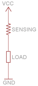
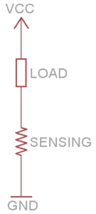
Low and High Side Current Sensing
Low side current sensing works by connecting the current sensing resistor between the load and the ground, hence the term “low side”. The voltage dropped across the resistor is measured, typically by an op-amp.
Low side sensing is cheap and easy to implement. For high precision, consider using a chip such as the OPA335. The typical disadvantage of low-side sensing is the extra disturbance in the ground path.
High-side current sensing works much the same way, although the resistor is placed between the power source and load.
Discrete Transistor-Based Current Limiting Circuit:
However all the above designs require some sort of processing – a computer is needed to make a decision based upon measurement. The following implementation uses a few low cost, discrete components to prevent excessive current from damaging the motor in a stall condition. There isn’t any decision-making by a microprocessor here, instead, a current feedback loop is created by Q2, which monitors the voltage drop across R1.
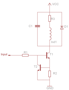
Operating principle:
- If T1 is open, current flows through R1, the “current sensing” resistor.
- The voltage drop across R1 increases as the current through T1 increases (Ohm’s law).
- If the voltage drop across R1 reaches ~0.65V, T2 begins to open (assuming transistors are 2N3904).
- Some current diverted to Gnd through Q2, less through A1
C1 is an optional EMI suppressing capacitor, and D1 is an optional diode to prevent damage to T1 from large back EMF.
Including the motor equivalent circuit (stalled, so no back emf) we have:
In the steady-state, the inductor has no influence.
Component values should be chosen such that the T2 will open when the current is just above the Maximum Start Current, as listed on the product datasheets.
Although this circuit is suitable for low-power applications, it is less so for DC motors. The circuit reduces heat dissipated in the motor by dissipating it in the transistors. For our range of gearmotors, this would be around 1-15W, which could cause catastrophic component failure.
Configure an Adjustable Voltage Regulator as a Current Regulator
An alternative implementation that also doesn’t require a microprocessor is to use an adjustable voltage regulator in a current limiting configuration. Let’s use the LM317 as an example, which is a 3 pin voltage regulator with a wide range of input voltages (3-40V).
By connecting a fixed resistor between the adjust and output pins, the maximum current limit can be set according to a simple equation (please consult the manufacturer’s datasheet for further information regarding the LM317). Additionally, an optional output capacitor can be added to improve the transient response of the limiter.
Again, as a designer, you should be careful of overheating when using the part in this way.

Get in touch
Speak to a member of our team.
Motor catalogue
Looking for our products?
Reliable, cost-effective miniature mechanisms and motors that meet your application demands.
Newsletter
Sign up to receive new blogs, case studies and resources – directly to your inbox.

Sign up
Discover more
Resources and guides
Discover our product application notes, design guides, news and case studies.
Case studies
Explore our collection of case studies, examples of our products in a range of applications.
Precision Microdrives
Whether you need a motor component, or a fully validated and tested complex mechanism – we’re here to help. Find out more about our company.