High Side Current Sensing for DC Motors
This blog post describes a simple and accurate way to measure the current in a DC motor circuit.
Perhaps the most obvious method for measuring current is to use an ammeter. However should you wish to plot the current overtime on an oscilloscope or measure the current with a microcontroller, it is necessary to convert this current to a voltage. One method is simply to purchase a current sensing IC, however, the same functionality can be achieved with a few common components.
The simplest I-V converter is a resistor. However, the terminal resistance of a miniature motor is very low, typically just a few Ohms. As a result, inserting a ‘sense’ resistor in series will result in a significant fraction of the supply voltage being dropped over that resistor unless the resistor value is very small. Perhaps then you would choose, say, a 0.1 Ω sense resistor. Choosing a resistor this small effectively reduces the gain of the I-V conversion – which is problematic if you require a 0-5V measurement range for a microcontroller. We can avoid this design conflict using the circuit below:
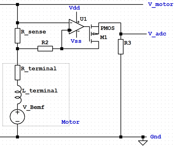
A low-value sense resistor, (R_{sense}), is placed in series with the motor. An op-amp alters the voltage at the gate of the MOSFET to permit a current flow through (R_{2}) such (V_{R_{2}}) is equal to (V_{R_{sense}}).
This current also flows through the resistor (R_{3}). We can, therefore, alter the gain of this circuit by adjusting the values of (R_{2}) and (R_{1}) according to:
$$V_{adc} = V_{shunt} times frac{R3}{R2}$$
The error in this measurement is given by:
$$ Error_{Total} = Error_{R2} + Error_{R3} + frac{ offset}{ V_{shunt}}$$
Note that for a DC motor, the trace of (V_{adc}) as viewed on an oscilloscope will exhibit spikes from the periodic connection and disconnection of by the commutator – the same spikes that can be used to measure motor speed. It is desirable to smooth this trace to avoid incorrect readings by the microcontroller. This is easily achieved with the inclusion of a low pass filter on the output, (V_{adc}).
Circuit description, schematic and idea from Intersil’s “Precision Analog Cookbook”.

Get in touch
Speak to a member of our team.
Motor catalogue
Looking for our products?
Reliable, cost-effective miniature mechanisms and motors that meet your application demands.
Newsletter
Sign up to receive new blogs, case studies and resources – directly to your inbox.

Sign up
Discover more
Resources and guides
Discover our product application notes, design guides, news and case studies.
Case studies
Explore our collection of case studies, examples of our products in a range of applications.
Precision Microdrives
Whether you need a motor component, or a fully validated and tested complex mechanism – we’re here to help. Find out more about our company.