Haptic Evaluation Kit Tutorial: Building Your Own Vibration Alerts
Looking for our Haptics range? View our main Haptics hub here.
Development Mode Series: Building Your Own Vibration Alerts
Note: This article discusses using the MOSFET to play vibration alerts. Therefore it’s only applicable to ERMs and not LRAs, more on this in the limitations section.
Those who have explored the Engineering Mode will have seen we include the functionality for building your own vibration alert waveform in the menu system.
It’s a very simple interface, select the waveform and peak output power along with the duration the effect is played over and the time between effects.
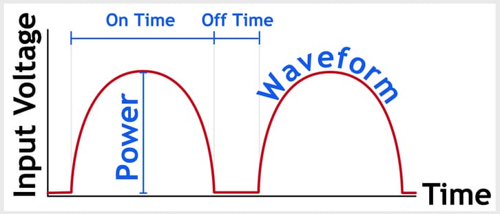
In the Development Mode, you can implement the exact same functionality using the playVibAlert( waveform , pwr , onTime , offTime); function.
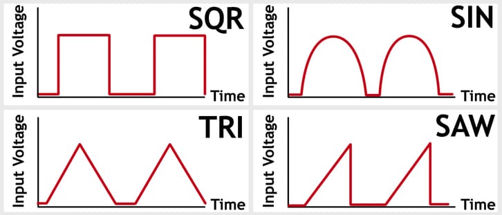
Both the On Time and the Off Time are measured in tenths of seconds, the power is a percentage of the maximum for the motor (explained below) but the waveform is an integer (0 – 3) that specifies the vibration pattern:
0 = Square Wave
1 = Sine Wave
2 = Triangle Wave
3 = Sawtooth Wave
With these 4 parameters, you can create a wide range of vibration alerts and even play different waveforms back to back, all from calling one function. The only requirements playVibAlert();; are that you have already calledselectMotor( motorID );autoCalibrate(); if you are using one of the motors in the Haptic Grip.
Of course, if you want to use your own external actuator then that’s ok too – you can use the functionality of DRV2605.cpp to call drv2605.autoCal (rated voltage, overdriveClamp, LRA, compensation, backEMF, feedback); to manually set the rated voltage and the overdrive voltage of the ERM. However you will need to build some external circuitry as the OUT- and OUT+ pins on the Haptic Shield do not connect to the MOSFET.
How PlayVibAlert(); Waveforms Are Processed
Looking at the code for the functionplayvibAlert(); in motor.cpp, it may be easy to be confused. However, the main principle is quite simple, calculate how frequently the power will be changed for that waveform during the On Time and then perform the power calculation.
Our function is built to support different types of waveform, if you intend to only use one then a lot of the complexity is removed.
For example, a square wave will only need the power calculated twice (once to switch on and once to switch off) regardless of the On Time. Not only will a sine wave need to calculate the power more times to create a nice smooth waveform, but the period between power calculations is dependant upon the On Time.
Once we know how often we are calculating the power – we actually have to do it! The sine wave has the problem that the power increase and decrease is not a constant gradient, so we have to consider the resolution of our wave.
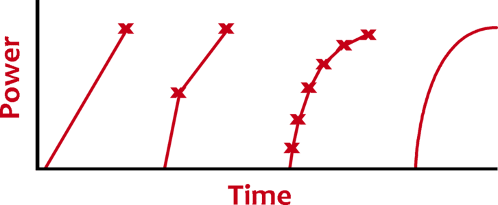
In the graph above we can see that we get a much smoother wave as we approach an infinite amount of power calculations, so what is a reasonable scale? We decided 11 points (including 0% and 100%) gave suitable resolution as vibration motors will naturally smooth out the curve to an extent, i.e. it doesn’t react instantaneously.
Does that mean we calculate the value of a sine wave 11 times within half of the On Time (remember the wave returns to zero, so the On Time covers the full rise and fall)? And then another 11 times as the wave falls to zero again?!
Well, we could – but don’t have to. Remember the On Time affects the period between power calculations, the result of the calculation should be the same every time. So instead we stored the values in an array, halfSineTable[] in motor.h, the power calculation becomes a simple lookup.
Implementing Your Own Waveform
analogWrite(); is the function for varying a PWM signal on the Arduino. If you want to manually handle everything, use this on pin 9 (which is connected to the MOSFET) to vary the voltage to the motor:
analogWrite( 9 , 255 ); // Full power on the MOSFET
Note: the value you can write with this function ranges between 0 and 255, corresponding to a 0 to 100% duty cycle with the maximum being 5V applied to the motor. i.e. value 127 = 50% = 2.5V and value 64 = 25% = 1.25V.
You can calculate the voltage you want to apply any way you want, pass the corresponding duty cycle into theanalogWrite(); function. You could use the same technique as we use for the sine wave, store the power values in an array and look them up in turn.
Alternatively, If you wanted to continue to use our playVibAlert(); function, you could adapt the motor.cpp file to suit your needs. Open motor.cpp and navigate to line 299 to see the start of the switch case statement, and after the sawtooth case enter your new case (4) from line 324.
If you liked how we did the sine wave why not copy it and simply change the array?
// Custom Waveform
case 4:
t /= 5; // reduce range to <0 , 20>
t -= 10; // move range from <0, 20> to <-10 ,10>
t = 10 – (abs( t )); // now range is 0-10-0
t = pgm_read_byte( &myTable[ t ]);
break;
Remember to change the name of the array, you’ll also need to create the new array with the correct name in motor.h (copy and adjust the halfsineTable[] on line 75):
static uint8_t __attribute__ ((progmem)) halfsineTable[]
={ 0 , 16 , 31 , 45 , 59 , 71 , 81 , 89 , 95 , 99 , 100 }; //full sine wave 20
static uint8_t __attribute__ ((progmem)) myTable[
]={ 100 , 84 , 69 , 55 , 41 , 29 , 19 , 11 , 5 , 1 , 0 }; // an ‘inverted’ sine wave
Above myTable[]; contains the values to drive a ‘reversed’ sign wave. Remember the values used for pwr are adjusted to represent the percentage of the duty cycle, and the function relies on the motor’s calibration function for output range (autoCal(); is explained at the start of this tutorial).
Want to make something totally different? What about creating a waveform that varies both the power and how long it stays at that power, i.e. varying the period between power calculations. Let’s consider the following array:
int myWaveform [] = { 100 , 30 , 80 , 30 , 60 , 30 , 40, 30 , 20 , 30 , 256};
We have alternated the stored values between the desired PWM strength with the amount of time (ms) that we want to play that effect for. For example, we will first drive 100% for 30ms, then 80% for 30ms, then 60% for 30ms, and so on. The total waveform takes 600ms, there are 5 different duty cycles each played for 30ms
256 is used as an exit code to signal we’ve reached the end of the waveform (it’s beyond the max duty cycle of 255, but you could pick any valid integer you wanted):
while (myWaveform[x] !=256)
{
pwr = (myWaveform[x] * 255) / 100 // adjusting the % value to PWM scaled
analogWrite( 9 , pwr );
x++;
delay(myWaveform[x]);
x++;
}
x = 0; // remember to reset x at some point
Limitations And Alternatives
You cannot use the playVibAlert(); or the analogWrite(); with an LRA. The former plays through the MOSFET on the Haptic Shield and therefore outputs a (variable) DC signal, the latter does not actually produce an analogue signal but a PWM – which again is DC.
LRAs require AC signals, the best way to drive them is through a chip like the DRV2605. They are great for haptic response and playing complicated waveforms. Vibration alerting is usually much simpler, the additional cost of an LRA may make it a less attractive option as an actuator.
A key issue with the above methods (including our playVibAlert(); function) is that whilst the vibration alert is being played, the processor is tied up. This means if your waveform is 1 ~ 2 seconds long, you are unable to perform other tasks like reading sensors or changing displays. Can you think of a way to process other events as this is ongoing? What about interrupts?
Finally, as noted above the OUT+ and OUT- test points connect directly to the DRV2605 output pins. Therefore, to play a vibration alert on an external actuator you need some additional external circuitry. See our full guide here.

Get in touch
Speak to a member of our team.
Motor catalogue
Looking for our products?
Reliable, cost-effective miniature mechanisms and motors that meet your application demands.
Newsletter
Sign up to receive new blogs, case studies and resources – directly to your inbox.

Sign up
Discover more
Resources and guides
Discover our product application notes, design guides, news and case studies.
Case studies
Explore our collection of case studies, examples of our products in a range of applications.
Precision Microdrives
Whether you need a motor component, or a fully validated and tested complex mechanism – we’re here to help. Find out more about our company.