AB-011
Electrical Techniques For Using Different Power Sources
Overview
As vibration motors have a wide variety of applications, they are often integrated into systems that have different power sources. A common concern, in terms of power supply, is adjusting the source power supply voltage to a suitable level for the vibration motor or drive circuitry. This protects the motor and can ensure a constant level of performance for uses like haptic feedback.
Our vibration motors are all DC powered and have rated voltages ranging from 1.5V to 24V, with most operating in the lower end of the spectrum. This is often less than the system’s power supply voltage and further steps are required to reduce the supply voltage to the vibration motor to avoid damaging it.
For applications which are powered by batteries, such as handheld equipment, the voltage supply may not be constant. Although batteries are often specified by a nominal voltage, almost all battery chemistries fluctuate depending on their level of charge. This can impact on the performance of the vibration motor.
Therefore this Application Bulletin is aimed at discussing popular techniques for powering vibration motors from different, and in some cases fluctuating power sources. We’ve already covered how motors are driven in mobile phones, and in this bulletin, we have assumed that the output of the power circuit would be connected directly to the motor via a discrete driver or h-bridge.

Get in touch
Speak to a member of our team.
Motor catalogue
Looking for our products?
Reliable, cost-effective miniature mechanisms and motors that meet your application demands.
Potential Divider

The potential divider is a very simple and cheap method for reducing a voltage and can be calculated using Ohm’s Law. It is created by placing a resistor in series with the motor, then some of the supply voltage appears across the new resistor, R1, and the rest falls across the motor.
Analysis of the circuit is not completely straightforward because of the motor’s ‘back electromotive force’, or EMF. This is created by the rotation of the motor through its internal magnetic field and appears as a voltage source in the opposite direction to the supply voltage. See the equivalent circuit for DC operation below. Unfortunately accounting for the EMF is difficult because it varies with the speed of the motor.
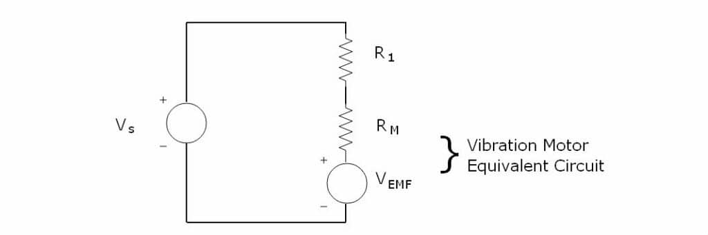
Thankfully with the information supplied in our comprehensive datasheets and a simple reduction in the circuit, you are able to find a value for the series resistor for each of our vibration motors.
The value of 𝑅1 must be low enough that the motor’s voltage is above the Certified Start Voltage, but high enough so it does not exceed the Maximum Operating Voltage. We can also remove the EMF from the equation. For the maximum value of 𝑅1 (ensuring the motor reaches the Certified Start Voltage), we consider the circuit when the motor has not yet started turning, which means the EMF is zero. In addition, for the minimum value of 𝑅1 (ensuring the motor does not exceed the Maximum Operating Voltage), we consider the worst case, which is when the motor operates at its maximum resistance. This is also when the EMF equals zero.
We can then reduce the circuit to a simple voltage divider equation, where the upper and lower values of 𝑅1 are bound by the following:𝑅𝑀𝑉𝑠−𝑉𝑚𝑎𝑥𝑉𝑚𝑎𝑥≤𝑅1≤𝑅𝑀𝑉𝑠−𝑉𝑠𝑡𝑎𝑟𝑡𝑉𝑠𝑡𝑎𝑟𝑡
Where:
𝑅1 is the series resistor
𝑅𝑀 is the value of Typical Maximum Terminal Resistance (in vibration motor’s datasheet)
𝑉𝑠 is the supply voltage
𝑉𝑠𝑡𝑎𝑟𝑡 is the value Certified Start Voltage (in vibration motor’s datasheet)
𝑉𝑚𝑎𝑥 is the value of Maximum Operating Voltage (in vibration motor’s datasheet)
Please note: These are theoretical limits and are based on typical values. You should always test your system thoroughly and work well within these limits using an appropriate safety factor.
As an example, if we were trying to drive the 304-103 SMD vibration motor from a 15V supply, we could use the equation above to calculate the minimum and maximum values of 𝑅1.
𝑅1 Maximum𝑅1≤𝑅𝑀𝑉𝑠−𝑉𝑠𝑡𝑎𝑟𝑡𝑉𝑠𝑡𝑎𝑟𝑡𝑅1≤34Ω15𝑉–1.8𝑉1.8𝑉𝑅1≤249Ω
𝑅1 Minimum𝑅1≥𝑅𝑀𝑉𝑠−𝑉𝑚𝑎𝑥𝑉𝑚𝑎𝑥𝑅1≥34Ω15𝑉−3.2𝑉3.2𝑉𝑅1≥125Ω
It is also important to calculate the power dissipated through the series resistor, to ensure it is of a suitable power rating. The calculation is straightforward, as the Maximum Operating Current for the selected motor is also found in the datasheet.
Continuing with the example of the 304-103, using the maximum value for 𝑅1 allowed:𝑃𝑅1=𝑖2𝑅1𝑃𝑅1=(75𝑚𝐴)2×249Ω𝑃𝑅1=1.4𝑊
Determining the power rating of the resistor required to handle this level of power dissipation is beyond the scope of this article, but there are plenty of articles on the web that can help. We can also see from the equation above that choosing a smaller value for 𝑅1 can decrease the minimum power rating.
Series Diode

This is possibly the simplest method for reducing the supply voltage by a fixed amount. It works by placing a silicon diode in series with the power supply and motor, which causes the diode to work in its normal forward biased region.
In this operation, the diode has a voltage drop of 0.6V – 0.7V, regardless of supply voltage. This is a great solution if the supply voltage is just above the Maximum Operating Voltage of the vibration motor, or within 0.6V.
This may seem like a rare occurrence, however many of our motors are rated at 3V with a Maximum Operating Voltage of ~3.6V. These vibrating motors are often used in handheld and mobility applications, where lithium-ion batteries are a popular choice of power source. These are mainly in the 3.6V – 4.2V range (depending on charge), making the series diode method a perfect low cost, low footprint solution.
Power dissipation in the diode is also an issue, but for example, a typical motor might take 100mA, with 0.6v across the diode, leading to a 60mW power dissipation, which should be within the scope of many small footprint diodes.
Zener Diode
The ideal diode does not allow any current to pass when a voltage is applied in the reverse direction, acting as an open circuit. In reality, diodes have a “breakdown region”. This is when the reverse voltage is large enough that the diode breaks down and allows current to flow. Zener diodes are designed to operate in this region where they have a near constant voltage drop, which is known as the breakdown voltage or Zener voltage.
Some simpler circuits use a Zener diode in series with the load. The required breakdown voltage of the diode would be equal to the supply voltage minus the desired voltage across the load. For vibration motors, this design may not be desirable as the diode could become hot as there is a large current passing through it.
A preferred method is to use a load connected in parallel with the diode, whereupon the Zener will ‘clamp’ the voltage across the load. This means that even under a variable power source, as long as the source voltage is greater than the Zener diode’s breakdown voltage, the load will have a steady voltage supply. Note that the Zener voltage is dependant upon the current flowing through the device, and therefore the voltage supplied to the load can also fluctuate a little.
Power dissipation in the Zener is something to be considered and generally, there’s a graph on the Zener datasheet that can be used to determine the power dissipation based on current.
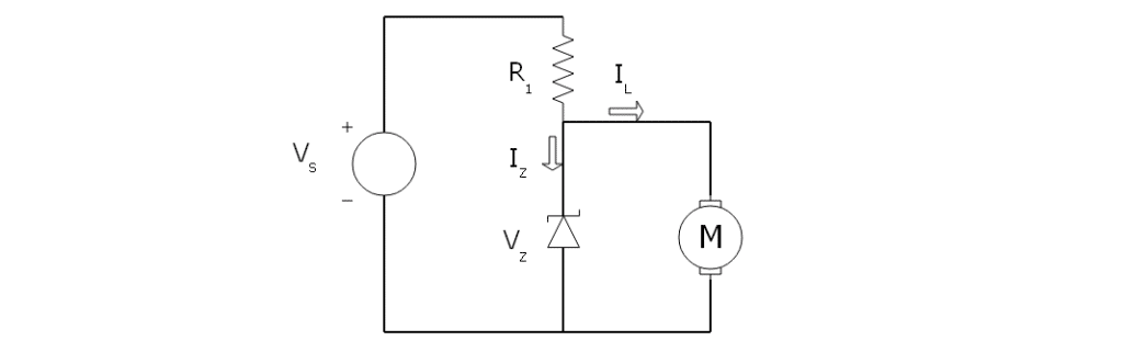
A schematic of a typical Zener diode regulation circuit is shown to the right. As Zener diodes are designed to operate in the breakdown region, they point in the opposite direction to normal diodes in schematics, with the anode connected to the ground or negative terminal.
To limit the current and dissipate excess voltage, a resistor is placed in series with the power supply. The value of the resistor 𝑅1 is calculated as follows:𝑅1=𝑉𝑆–𝑉𝑍𝐼𝑍+𝐼𝐿
Where:
𝑉𝑆 is the supply voltage
𝑅1 is the Zener diode’s breakdown voltage
𝐼𝑍 is the current through the Zener diode (taken from diode’s datasheet)
𝐼𝐿 is the current drawn by the motor, the value Typical Operating Current
We saw this technique used in Application Bulletin 008: Vibration Motor Best Practices from the Mobile/Cell Phone Industry.
LDO Voltage Regulators
Low drop-out (LDO) voltage regulators are widely packaged as integrated circuits. Many of them can accept a range of input voltages and output a reduced constant voltage. The value of the output voltage depends on the specific regulator, but there are many that are designed to be adjusted with a couple of external components.
LDO regulators can be used to ensure a constant vibration alerting amplitude in battery-powered applications, where the varying charge levels of the battery would otherwise cause a varying vibration motor performance.
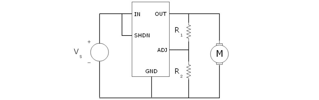
This example is based around an LT3060. A potential divider is used to adjust the output voltage, values used will be dependant on the specific regulator. Linear regulators tend to be based on a Zener diode/transistor design with a feedback loop to adjust the output voltage.
Most regulators also included a shutdown (SHDN) pin, which can be used to shutdown the regulator (saving power) and by inference, turn the motor on and off.
An alternative to linear regulators is switching mode power stepping designs which are more power efficient than linear regulators. However given that the vibration motor is not often driven continuously, they are rarely worth the additional expense or PCB real-estate.
Dedicated Motor Driver ICs
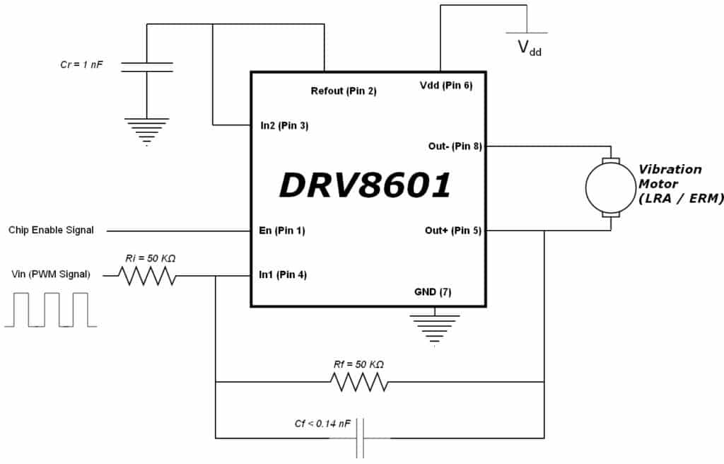
Motor drive integrated circuits are often the easiest way to drive a motor, though not the cheapest. They can accept a range of input voltages, output different voltage levels, accept a variety of control signals, and are often very well documented. Information on the IC’s conformity limits will be detailed in their datasheets, and they also often include application notes for customisations.
In Application Bulletin 003 we looked at certain chips aimed at driving Linear Resonant Actuators. Many of these devices also supported ERM vibration motors and included application notes for extra customisation.
Conclusion
Powering a vibration motor’s drive circuitry directly from a power source is not always possible, as often the motor’s maximum rated voltage is below that of many power supplies. Even if a DC voltage bus is readily available, there may be other circuitry in the application that uses a significantly higher voltage than the vibration motor. Problems can also arise from battery voltage sources, as the supply voltage may fluctuate and lead to reduced performance.
Fortunately, it is much easier to regulate the voltage down than to boost it up, and we have demonstrated some of the popular circuit techniques for connecting higher voltage fluctuating power sources to vibration motors.
Reducing and stabilising the supply voltage can be performed using discrete components or integrated circuits. Above we have provided example circuits and formulae for calculating important component values. We have also discussed popular ICs and linked to separate Application Bulletins which further expand on the topic.
Newsletter
Sign up to receive new blogs, case studies and resources – directly to your inbox.

Sign up
Discover more
Resources and guides
Discover our product application notes, design guides, news and case studies.
Case studies
Explore our collection of case studies, examples of our products in a range of applications.
Precision Microdrives
Whether you need a motor component, or a fully validated and tested complex mechanism – we’re here to help. Find out more about our company.