Driving Multiple Actuators from a Single Source
Introduction
If you are looking to run more than a single motor from a driver or MOSFET you may be concerned with the additional power consumption and exactly what happens in the circuit.
We’ll look at series and parallel connections, highlighting what this means for drivers. In addition, there’s a special note at the bottom discussing multiple LRAs.
Series Connection
A connection of multiple motors in series would look like this (note this is for steady-state analysis, we’ve excluded the back EMF):
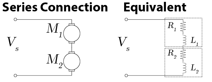
As we can see from the equivalent circuit above, we are increasing the overall resistance and inductance. As you would intuitively expect the overall current flow is reduced as the overall impedance is increased.
The voltage drop is shared across each motor, if all motors are the same model (or similar specs) then they voltage is shared equally. For example, two of the same motor connected to a 3V source will each perform as if they were driven with 1.5V:
For one motor:
$$V_{1} = I \times R_{1}$$
$$V_{1} = \frac {V_{s}}{R_{1}} \times R_{1}$$
$$V_{1} = V_{s}$$
For two motors in steady state \(V_{1} = V_{s} – V_{2}\)
$$V_{1} = ( I \times R_{T}) – (I \times R_{2})$$
$$V_{1} = I (R_{T} – R_{2})$$
$$V_{1} = \frac {V_{s} } { R_{T} } (R_{T} – R_{2})$$
$$V_{1} = \frac {V_{s}}{R_{T}} (R_{1} + R_{2} – R_{2})$$
$$V_{1} = \frac {V_{s}}{R_{T}} \times R_{1}$$
If the two motors are the same then
$$ R_{1} = R_{2}$$
and so
$$ R_{T} = 2 \times R_{1} = 2 \times R_{2}$$
Now we can rearrange our previous equation
$$V_{1} = \frac {V_{s}}{R_{T}} \times R_{1}$$
into
$$V_{1} = \frac {V_{s}}{2\times R_{1}} \times R_{1}$$
$$V_{1} = \frac {V_{s}}{2}$$
We can see adding in a second identical motor the voltage supply to the first motor is halved.
For applications that have a fixed load, such as vibration motors, this can be overcome by increasing the voltage applied, however, for applications with varying loads, it is a bit more of an issue. If one motor sees an increased load and slows down, the second motor will speed up – in a similar way to an automotive differential. If balancing or maintaining speed is important, a parallel connection is preferred.
Note the motors may not perform exactly alike, there is a degree of tolerance with all manufacturing. For most applications, the difference will be extremely slight and undetectable.
Parallel Connection
A connection of multiple motors in series would look like this (again, excluding the back EMF):
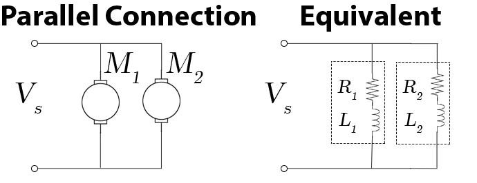
We saw with a series connection that the voltage to each motor would half (assuming two motors). However with a parallel connection, each branch will have the same voltage, so we will find adding in a second motor will double the current draw.
For a single motor the current draw is:
$$I_{1} = \frac{V_{s}}{R_{1}}$$
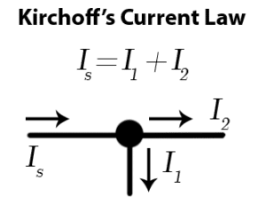
$$ I_{s} = \frac {V_{s}}{R_{1}} + \frac {V_{s}}{R_{2}}$$
Again
$$R_{1} = R_{2}$$
So
$$ I_{s} = \frac {V_{s}}{R_{1}} + \frac {V_{s}}{R_{1}}$$
$$ I_{s} = \frac {V_{s}+ V_{s}}{R_{1}} $$
$$ I_{s} = 2 \times \frac {V_{s}}{R_{1}} $$
The current draw with DC motors can be difficult to understand as it varies over time, spiking initially to overcome the inductance in the coils before settling to the steady state (as discussed shown above). It is also dependant upon the required torque, increasing the load will draw additional current.
Problems with Drivers
For DC motors (including gearmotors and ERMs) the problems are obvious, connecting in series requires more voltage and connecting in parallel draws more current.
Drivers will have a maximum output voltage (sometimes directly linked to the supply voltage), which often means a series connection is not possible. This is especially true for haptic drives that are almost exclusively designed for use with very low voltage (< 5V) motors.
When connecting in parallel, you will need to consider the equivalent resistance of each branch. Check your driver’s datasheet to see if it has a recommended minimum load impedance, additional resistors may be required if you find the parallel resistance drops too much.
As an example, the DRV2603 has a minimum load impedance of 8Ω.
Depending on the cost of your chosen driver, it may be the best approach to use a dedicated driver for each actuator.
Problems Driving Multiple LRAs
There is an additional concern for drivers that use auto-resonance tracking for LRAs. This is a closed-loop operation, relying on careful measurement of the LRA’s performance. These drivers do not expect multiple actuators and as a result will produce erroneous results, leading to reduced performance.
We would strongly recommend using an individual driver for each LRA. For more specific information about the Texas Instruments DRV2603, you may find this post on the e2e forum useful.

Get in touch
Speak to a member of our team.
Motor catalogue
Looking for our products?
Reliable, cost-effective miniature mechanisms and motors that meet your application demands.
Newsletter
Sign up to receive new blogs, case studies and resources – directly to your inbox.

Sign up
Discover more
Resources and guides
Discover our product application notes, design guides, news and case studies.
Case studies
Explore our collection of case studies, examples of our products in a range of applications.
Precision Microdrives
Whether you need a motor component, or a fully validated and tested complex mechanism – we’re here to help. Find out more about our company.