Design Guidance for Haptic Wearables
Looking for our Haptics range? View our main Haptics hub here.
We’re seeing a great number of startups and early projects looking for design advice. In part this is thanks to advancements and cost reduction in 3D printing, but also the general adoption of crowdfunding has provided small companies and individuals with more opportunities to get their idea off the ground. The barriers to developing a working prototype are lower than ever.
This has also coupled with a rise in the wearables market, in part thanks to low power Bluetooth and processor efficiency dramatically increasing the possible battery life. In the past year, big brands like Motorola, Pebble, LG, Sony and Apple have released smartwatches, but activity trackers like Fitbit and Jawbone’s UP also come under the ‘wearable’ umbrella.
For companies who are considering venturing into the wearables market, whether you’re looking at a new product line or an entirely new start-up, Precision Microdrives have a couple of key advantages that make us a valuable partner:
- Many of our motors are available without a Minimum Order Quantity (MOQ) – just making 5 prototypes? We can help.
- Our supply is scalable – 1k units in the first year? 25k? 500k+? We can help.
- We offer design assistance and the UK or Hong Kong-based engineering support – need advice with electronics or mechanical mounting? We can help.
- With offices in China, aside from our own production and testing, we have solid relationships with a variety of factories – having trouble or inexperienced in managing production in Eastern factories? We can help.
As for general ‘wearables’ advice, we’ve discussed some of the key points below.
ERM Amplitude vs Size vs Power Consumption
In offering this advice, we’re making a couple of assumptions based upon our experience with customers developing for the wearables market. Many of these come from the fact that wearables are almost exclusively extremely light. This makes sense, it would be difficult to convince a customer to carry a 1kg accessory – never mind wear one!
Making the device as light as possible often focuses on reducing its size. This means every component has a strict space requirement, including the battery. This is a particularly challenging area because smaller batteries have reduced power capabilities, and time between charges is a key area of competition for many wearables. For example, you may not sell many smartwatches if the battery doesn’t at least last the full day. These constraints lead to designers trying to squeeze as much life out of their battery as possible.
The vibration motor and its drive circuitry are no exception and vibration efficiency becomes an important design area.
Light and small wearables mean that we can afford a lighter amplitude motor, but it must be small in size. This introduces a tradeoff in terms of power consumption. A motor can reduce its current consumption by reducing the level of required torque relative to its power capability. Essentially, it draws less current with either a smaller mass or driven at a reduced speed.
However, by also reducing the motor’s body the possible output torque is also reduced. This means the motor will draw more current to generate the same vibration amplitude, which must still be of a sufficient level to notify the user. This ‘sufficient level’ will vary depending on a range of usage scenarios, for example, if the product is worn over clothes, during activities, its total weight, etc.
Therefore, we recommend looking at a variety of options in early prototyping – the smallest vibration motor is not always the most efficient. In addition, motors have a Rated Voltage but are able to operate at a range of voltages underneath this value (down to a point, Maximum Start Voltage). Check the datasheets and Typical Performance Characteristics graph to see how motors perform across a range of voltages – you may find a larger motor driven at a lower voltage is best for your application.
Haptic Feedback
Here we have a simple trade-off between functionality and power consumption/PCB complexity. You will need an additional component to drive the motor from a microcontroller, the cheapest and smallest would be a transistor. The circuit for a transistor will be simpler than that of a haptic driver, however haptic drivers enable you to easily deliver a wide range of vibration effects and patterns.
Also, if you would prefer to create your own vibration patterns, depending on how complex they are and how you generate them, you may be running your processor at a higher rate than if you sent a simple I2C command to a driver – thereby not saving much power overall. I2C has another distinct advantage in that the processor is free for other tasks whilst the effect is playing, unlike when using PWM control.
Haptic drivers like the DRV2605 are extremely efficient and are available as tiny ball gate array packages. Our advice is that the added functionality of a specialised haptic driver greatly outweighs the (very small) drawbacks, especially in a wearable where the primary communication with the user is vibration.
ERM or LRA?
If you’re not using a haptic chip, an ERM will be much easier to drive. If you are using a haptic chip then an LRA has a couple of great advantages:
- Excellent haptic response
- Highly efficient
- No external moving parts (easier to mount)
- Don’t suffer from the same mechanical wear as DC motors, leading to fewer failures and greatly increased lifetime
Whilst these benefits are fantastic, LRAs do have a higher cost than ERMs. How price sensitive is your target market? It’s worth noting that as volume increases (~10k+), the unit costs can start to become very similar.
Mounting Considerations
As noted in the LRA’s benefits above, external moving parts can be a problem. If you use an ERM, you need to ensure the rotating mass is not impeded. If the casing is too close, it can cause an audible rattle as the mass hits it every rotation. Even worse, it could stop it from working altogether.
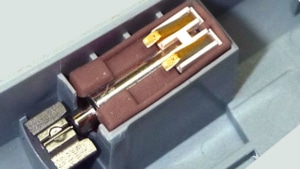
Each form factor has its benefits. SMD motors are great for economies of scale in pick and place machines, whilst the image on the right shows a spring terminal motor with supportive housing. This holds the ERM in place, transfers vibrations directly to the casing, and with no soldering, the unit is very serviceable.
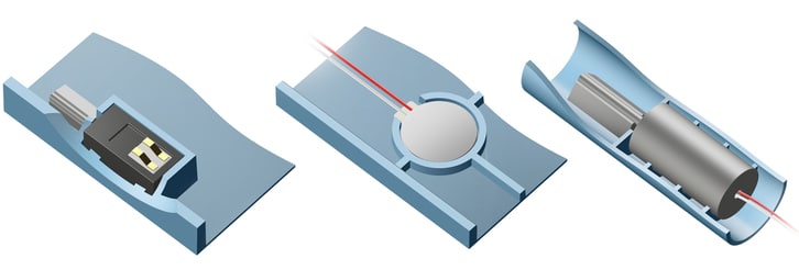
Alternatively, you may select a ‘coin’ form factor which is available as ERM or LRA. With an adhesive backing, these can be easily mounted anywhere, the image below suggests reinforced walls for stability.
To help with your design, we can provide 3D files for all of our parts. Simply contact us to request them from an engineer. We also have a full Application Bulletin discussing mounting in moulded enclosures which you can access here:
AB-015: Mechanical Mounting for Vibration Motors: Moulded and Machined Enclosures
Of course, if you need specific design advice or are looking for customisations – the best thing to do is to contact us for help with your application!

Get in touch
Speak to a member of our team.
Motor catalogue
Looking for our products?
Reliable, cost-effective miniature mechanisms and motors that meet your application demands.
Newsletter
Sign up to receive new blogs, case studies and resources – directly to your inbox.

Sign up
Discover more
Resources and guides
Discover our product application notes, design guides, news and case studies.
Case studies
Explore our collection of case studies, examples of our products in a range of applications.
Precision Microdrives
Whether you need a motor component, or a fully validated and tested complex mechanism – we’re here to help. Find out more about our company.