Decay Modes for Motor H-Bridge Drivers
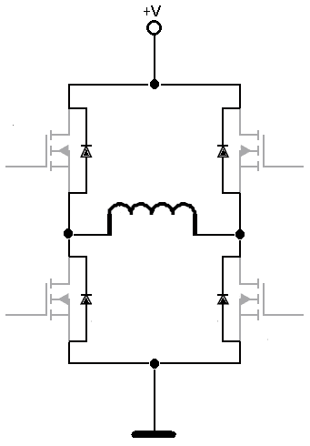
Recently we had a few customers asking about driving our DC gear motors with H-bridges, and specifically, whether they would need additional fly-back diodes for each transistor in the bridge. As it happens – you don’t, and there are a few options that can be arranged ‘for free’ by some small modifications to the timing of the drive signals to the transistors in the bridge.
What is Decay?
Decay is the re-circulation of current within a motor driver that uses pulse-width modulation (PMW). The inductive nature of DC motors means that they will oppose any change in the current run through them. Therefore, when the current is terminated, the resulting spikes in voltage can potentially damage the driver. This is particularly the case with micro-stepped stepper motors but applies to any position control system that utilises a brushed DC motor where a fast response time is desired. Moreover, it is not uncommon for such integrated circuits to be configured to offer both ‘fast’ and ‘slow’ modes of dealing with decay.
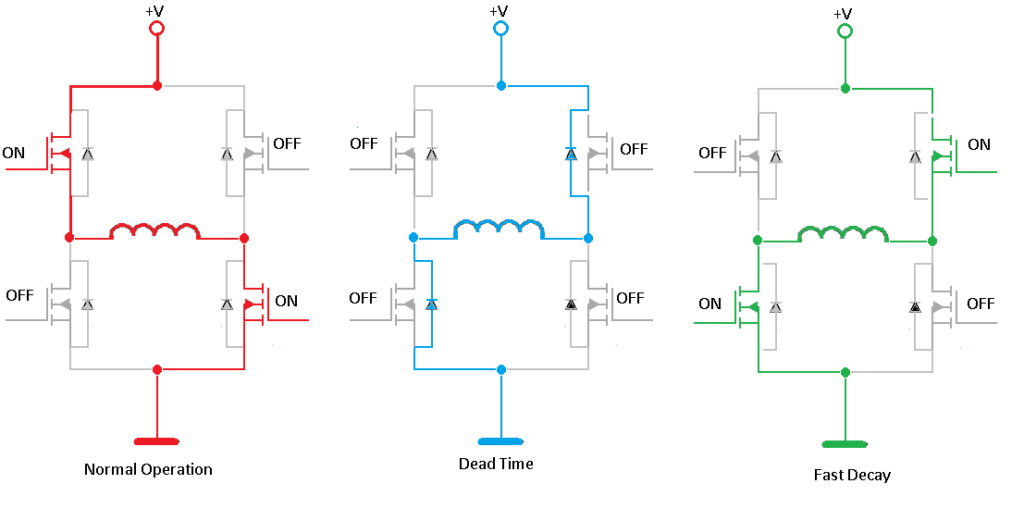
In most applications, this is achieved via freewheeling diodes. Within MOSFETs, such diodes are considered a parasitic element, but they offer good parameters and start conducting as soon as the FET switches are disabled. This is sufficient for most applications. However, when a faster motor response is required, a better way to handle the current is to set the FET switches in a sequence that enables the current to decay faster. This mode of operation is described as being asynchronous. Note that the main caution with this technique is making sure that the high and low side of the bridge are not switched on at the same time (know as ‘shoot-through’)!;
Conversely, where Back Electromotive Force (BEMF) is being used to induce a measurable speed signal, a faster rate of decay can be achieved by utilising MOSFET ON resistance in its place. Regardless of whether one uses either a fast or slow mode, this synchronous method is quicker than the asynchronous diode-based approach.
Because such transistors cannot be instantaneously turned either ON or OFF, there is a risk of cross-conducting. The transistors must be switched off to allow the current to flow through the diodes freely. This safe period is known as ‘dead time’ and can be calculated from the information in the transistor datasheet.
Fast Decay
In the case of fast decay, the voltage in the circuit is reversed across the windings, which decreases the current at a much faster rate. In regards to DC motors, this is essential to prevent the motor from failing. The limitation of this technique, however, is that it produces a high power supply current ripple.
Slow Decay
With slow decay, the current path can be delineated by either two low-side or two high-side MOSFETs connected in series. The decay in current is then defined according to the LR time constant, where R is a series connection of two MOSFETs Rdson.;
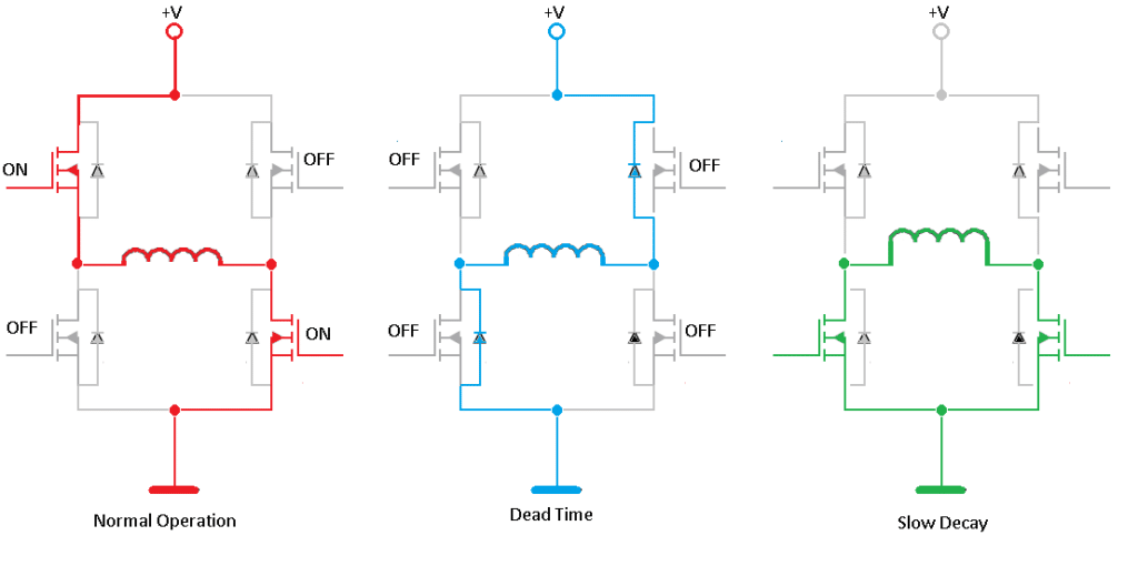
As the name suggests, the rate of decay here is slower but does not induce the spikes in current that are incurred when the circuit is reversed. When driving DC motors, the period of decay should nonetheless be limited as the rotation of the motor induces Back Electromotive Force (BEMF), which can short the windings causing the motor to fail.

Get in touch
Speak to a member of our team.
Motor catalogue
Looking for our products?
Reliable, cost-effective miniature mechanisms and motors that meet your application demands.
Newsletter
Sign up to receive new blogs, case studies and resources – directly to your inbox.

Sign up
Discover more
Resources and guides
Discover our product application notes, design guides, news and case studies.
Case studies
Explore our collection of case studies, examples of our products in a range of applications.
Precision Microdrives
Whether you need a motor component, or a fully validated and tested complex mechanism – we’re here to help. Find out more about our company.