AB-032
DC Motors – Voltage Vs. Output Speed Vs. Torque
The relationship between voltage, torque and output speed is a common topic of discussion between our customers and Precision Microdrives’ sales engineers.
The following article aims to discuss and elaborate on the relationship between these parameters and methods of using them together with other resources, to understand the full capabilities of our DC motors and gear motors.
Definitions of terms used in our data sheet can be found below with links generously distributed across the article for further reading.
Torque And Speed
Torque can be defined as a ‘twisting force’ that has a tendency to rotate an object about a fulcrum. In relation to DC motors and gear motors, we will typically refer to the ‘Rated Torque’ as the ‘Rated Load’ to avoid any confusion in our values. Ultimately, the two terms represent the same value – the rotational force applied to the output shaft.
When discussing ‘speed’, we are typically referring to the angular velocity of the output shaft on our DC motors and gear motors (typically in revolutions per minute). Depending on the application, this parameter will affect the rate at which a particular function is executed and it may have a significant effect on the overall performance of the device.
Why Change Torque?
The most obvious benefit of varying the torque is to maintain a constant speed when the motor’s load varies, keeping in mind the interdependent nature of speed, torque, and voltage.
Although this example may be outdated, audio cassettes are a great way of explaining how some applications need to vary the torque to match a changing load. As the cassette plays and the audiotape moves from one spindle to the other, the driving motor will experience a change in load. However, the playback must remain at a constant speed throughout – otherwise the audio pitch would be affected.
There are also instances where the motor’s load is changed dramatically between operations, rather than a slow dynamic change like the cassette example. Pulleys and lifts often experience this, the motor stops at an extremity as the load is attached or removed. Here, keeping a constant speed is not as important as the motor being able to handle a range of different torque loads as moving a heavier object requires more output torque than a light object or no load.
Each of these applications has the common theme of a varying load attached to the motor. If your application involves a fixed load, then it is likely that you will be more interested in varying the speed.

Get in touch
Speak to a member of our team.
Motor catalogue
Looking for our products?
Reliable, cost-effective miniature mechanisms and motors that meet your application demands.
Why Change Speed?
The ability to vary motor speed whilst maintaining a steady torque is essential to many applications for a variety of reasons.
An example of an application that requires a variable speed and steady torque is an audio CD player as it is commonly observed that the CD will rotate faster at certain points than others. This is because the information is stored in spiralled circular tracks on the disk and the length/circumference of the track is directly proportional to the amount of information stored on them. This means that the speed must be decreased as the laser is reading from the outermost tracks because there is more information per revolution. Inversely, the speed is increased as the laser reads from the innermost tracks as the spiral circumferences are smaller and therefore contain less information per revolution.
Without the ability to adjust the motor speed (with the voltage) whilst maintaining this constant torque, it would be very difficult to read and play this information at a steady rate.
This same principle can be applied to a wide variety of applications and is often critical to their successful operation. Many of our DC motors and gear motors can operate across a wide variety of speeds and loads, this allows our customers to explore the possibilities of their project and usually reach a suitable solution with a single motor.
How To Read The Typical Performance Characteristics Chart
The Typical Performance Characteristics chart appears on the front page of each of our data sheets. This graph is an extremely useful tool that illustrates the typical behaviour of an individual motor.
As we have previously discussed, many of our customers are looking for a motor or gear motor that will operate at a given speed and load. One of the best places to find a solution is our online catalogue and we can always help to recommend suitable motors and discuss customisation options. As motor speed in DC motors and gear motors is primarily dictated by the load and driving voltage, the data sheet value for ‘Rated Speed’ is taken at a ‘Rated Voltage’ and a ‘Rated Load’. This means that the data sheet values for speed are taken under controlled and specific conditions and do not represent the full capabilities of any single motor. This is where the typical performance chart is a useful tool to view a wider range of the motor capabilities.
The graphs for our DC motors and Gearmotors assume a fixed voltage and show how current draw, power, efficiency and motor speed are affected by a change in load. Each of the affected parameters has it’s own independent performance line and corresponding scale on the Y-axis.
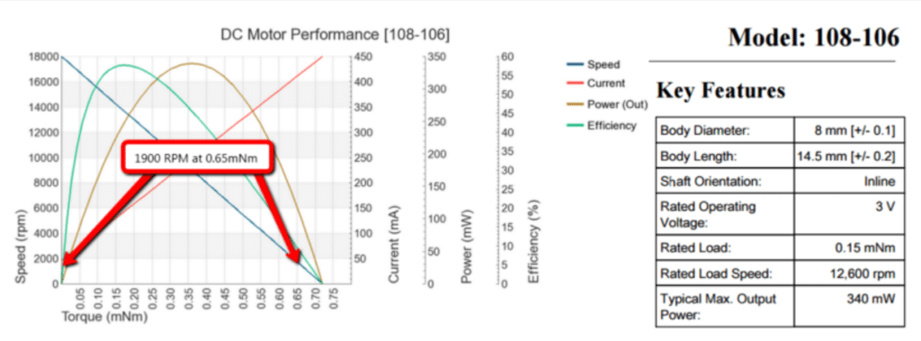
The blue line on the 108-106 Typical performance Chart (above) shows the speeds at which the motor will operate between a point of no-load all the way up to its stall torque (approx. 0.725 mNm) and allows us to examine the motor performance as well as understand the relationship between speed and torque for the individual motor.
For example; if a customer requires a steady speed and torque of 1900 RPM and 0.65 mNm respectively, the data sheet “key features” section (above) would indicate that the 108-106 was not suitable as it states:
Rated load – 0.15 mNm
Rated load speed – 12,600 RPM
However, after inspecting the performance chart, at a load of 0.65 mNm on the X-axis, the blue performance line (speed), indicates on the corresponding Y-axis that the speed will be 1900RPM. The image above illustrates this and demonstrates that the 108-106 is, in fact, suitable for the customer based on their fixed speed and torque requirements. This chart can also be extended to illustrate the range of capabilities for the motor if it is to be used with a dynamic load/speed.
The Relationship Between Speed, Torque And Voltage
Now that we’ve discussed how to read the performance chart, we can look at the relationship between speed and torque. In this section, we will outline the relationship between speed and torque and explain the limits of each before considering the further effect of voltage on these parameters.
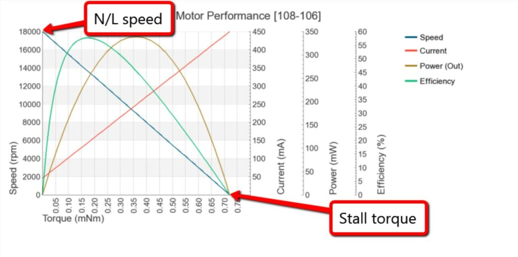
Assuming the motor is driven at a fixed voltage, there are two points that describe the peak performance of a motor at each extremity. “No-load speed” (N/L) and “stall torque”
- The stall torque represents the point at which the motor has reached its maximum operational load. At this point, the shaft will no longer rotate and the motor will be in a “stalled” condition. Please note that the motor must not be operated to stall as this will almost certainly lead to premature failure
- The no-load speed is the maximum output speed the motor will achieve at a given voltage. At this point, the motor is running freely and under no external load
Our DC motors and gear motors can operate anywhere between these limits before reaching stall. If we take a look at the blue performance line, the relationship between speed and torque is quite easily understood – the torque is inversely proportional to the motor speed – starting at the point of no-load/full speed and, as the load increases, the speed decreases proportionally until the motor stalls.
Whilst the performance chart illustrates how speed is affected when applying various loads, it does not indicate that the speed of our DC motors is also directly proportional to the voltage applied. The theory behind this principle can be found here. In short, this means that we can control the speed of a motor independently of the torque and it allows us to maintain a steady speed for a variable load and also maintain a steady torque with a varying motor speed.
This principle is employed to ensure that our CD player and cassette tape are played correctly and would probably include a closed-loop feedback system that will measure the motor speed and adjust the driving voltage to either maintain a steady speed for a variable load or provide a variable speed for a fixed load.
How We Can Change Motor Performance
There are several methods in which the performance of a motor can be customised, whether this is a highly customised solution tailored to a customer’s needs or a simple adjustment to how the motor is operated. Some common modifications are listed below:
- Windings: By modifying the number of turns in the motor coils and/or the cross-sectional area of the wire used, the terminal resistance, operating voltage/current and terminal inductance can be manipulated. This means that both the electrical and mechanical performance of a motor can be tailored to a particular specification quite easily
- Gearbox ratios: Gearboxes are an effective method of accurately altering DC motor performance using one or more gear stages. Whilst we do supply stock reduction gear motors, many of our customers like to develop their own set of gears. If you would like to experiment with your own gear chains, simple gear equations can be found in AB-024. However, we can offer custom gearboxes and stock part modifications so please feel free to contact an engineer if you would like to discuss your requirements and the options that we can offer.
- Driving voltage: This can be a simple and cost-effective way to control the performance of our motors. There are several ways in which you can adjust the driving voltage to your motor, including PWM and even dedicated driver IC’s. We have previously discussed these topics in more detail at the following links – 1 and 2
- Material selection: The materials used can significantly affect the overall performance of your gear motor. Some of the potential options here are listed below
- Gear material: A common point of failure with micro gear motors occurs at the final gear stage. This is the point at which the largest force is exerted when a load is applied to the motor. In this instance, the gear can fail long before the motor stall torque is achieved and the potential capabilities are not fully utilised. If this is the case, stronger gears can be added to the final stage(s) so that a higher torque and wider performance range can be achieved. In practice, this has been used with the 206-108 which stalls at roughly 17mNm due to gear failure. This is characterised on the characteristics chart by an abrupt halt in the torque-speed line long before stall (0 RPM) is approached. By inserting a metal gear at the final stage a torque of roughly 34mNm is achieved, doubling the torque capabilities of the motor and opening up a wider range of possibilities. This was given the part number 206-10C
- Lubricants: Ambient and operational temperature largely affect the efficiency of a gear motor and the overall performance achieved at the output shaft. Whilst the electrical efficiency of the motor can often increase at low temperatures, the gearbox efficiency and effectiveness of the lubricant can reduce such that the overall performance is lessened. A common method of reducing this effect is to use a specified cold temperature lubricant. This can increase the efficiency of the gearbox and therefore the performance of the motor at the output. This means that the temperature range listed on the datasheet is not an absolute limit and there are several ways that it can be extended. If there are any queries, Precision Microdrives engineers will be happy to help out
- Encoders: If you require greater control of your gearmotor or use it within a positioning actuator, you may require an encoder. This is a typical modification that we can offer ranging from simple tachometers for speed measurement, incremental encoders for single reference positioning, all the way to absolute encoders for exact positioning of the output shaft. These encoders can also be used in closed-loop control to maintain speed for a varying torque, vary the speed for a steady torque, or any combination of the two (examples discussed earlier in this article). Please do get in touch with a Precision Microdrives engineer if you would like further information on what we can supply
Any combination of the above can be used together to achieve a wide variety of outputs from our gear motors. So, even if you cannot find a gear motor performance chart that meets your specification, please feel free to contact our engineers as there are a variety of ways that we can look to meet your requirements.
Limitations
As with all good things, there are limitations to what can be achieved. This section aims to outline some of the associated limitations that are encountered when modifying a gear motor.
- Windings: Unfortunately, without significant modification and expense in developing a wire with a specific cross-sectional area, it is occasionally difficult to provide an exact performance at a required terminal resistance, operating voltage/current and terminal inductance. If this is the case, the requirements are often met very closely and the variations can be negligible. Dimensional limitations also apply here as very limited space is available for the windings. In practice, this means that certain mechanical/electrical performances cannot be achieved with a given motor due to the envelope available space for the windings and the required cross-sectional area/number of the winding wire. Of course, Precision Microdrives will be happy to assess the feasibility of your request, so please do not hesitate to contact us with your requirements
- Material properties: Material properties also represent a limitation when considering achievable modifications with our motors.
As discussed, cold temperature lubricants can be used to increase the performance of a material at certain temperatures, however, there are obvious physical limitations to specific materials. Notable limiting properties include the coefficient of thermal expansion, material strength, melting points and many others. If you do have any queries relating to this, please do get in touch
In this section, we have discussed a few of the obvious limitations that present themselves when modifying a gear motor. In many cases, these limitations are surpassable if less critical parameters are more flexible. So, please do enquire with our engineers to assess what can be implemented within your application.
Conclusion
Throughout this article, we have discussed some reasons why a user will vary motor speed and torque and looked at specific examples for each situation. This prompted us to consider the limits of motor speed and torque for our gear motors when driven at a fixed voltage. Here we understood that, at a fixed voltage, our motors can operate across a wide range of speeds and torques between a point of no-load (full speed) and the point of maximum load (stall).
We have also discussed how to read the “typical performance characteristics chart” to understand the full range of torque and speed capabilities of a given motor (at its rated voltage). From here we saw how the relationship between speed and torque is inversely proportional from a point of no-load to stall torque and discussed how we can adjust the driving voltage to maintain a steady speed or torque when the other variable is dynamic.
The final section of this bulletin was aimed at describing some methods of manipulating motor performance. Some of these methods are easily implemented and can be experimented with when testing, whilst others are permanent modifications that can be provided to a particular specification. If you would like to consider the options that you have for your project, please contact one of our engineers to discuss your requirements and the options that we can offer you.
Newsletter
Sign up to receive new blogs, case studies and resources – directly to your inbox.

Sign up
Discover more
Resources and guides
Discover our product application notes, design guides, news and case studies.
Case studies
Explore our collection of case studies, examples of our products in a range of applications.
Precision Microdrives
Whether you need a motor component, or a fully validated and tested complex mechanism – we’re here to help. Find out more about our company.