AB-022
PWM Frequency For Linear Motion Control
Introduction
Pulse Width Modulation (or PWM) is a popular and efficient method for driving DC motors because we can control the motors with significantly fewer power losses than continuous linear regulation.
Using PWM enables control of the current in the windings and in turn the output torque, as the torque is proportional to average winding current. It follows that current will be proportional to PWM because of the torque’s linear response.
In a circuit, resistive loads will have a current that is proportional to PWM. However DC motors are more complex than resistive loads, they contain an inductance and when rotating they produce back EMF.
These factors usually mean PWM control isn’t strictly linear, the PWM frequency (not just the duty cycle) is actually quite significant for output parameters.

Get in touch
Speak to a member of our team.
Motor catalogue
Looking for our products?
Reliable, cost-effective miniature mechanisms and motors that meet your application demands.
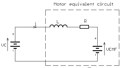
When the motor is at rest (or is rotating at a very low speed) then there is no back EMF (or it’s extremely small) and the circuit becomes simpler. In this situation, the current is limited by the resistance of the windings and the coil’s inductance.
As a side note, if the motor was operating from a regulated DC source, not PWM, then the current will be determined only by resistance as the inductance does not have an impedance with a constant source.
We’ve updated the equivalent circuit below to reflect the motor at low speed or no speed, consisting of only a series RL circuit.
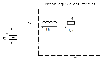
The input voltage V is equal to the sum of the voltage drop across the inductor and the voltage drop across the resistor:𝑉𝐿(𝑡)=𝑉𝑒−𝑡𝑅𝐿𝑉𝑅(𝑡)=𝑉(1−𝑒−𝑡𝑅𝐿)
The voltage across the inductor tends towards 0 as time passes, while the voltage across the resistor tends towards V. This is in keeping with the intuitive point that the inductor will only have a voltage across as long as the current in the circuit is changing — as the circuit reaches its steady-state, there is no further current change and ultimately no inductor voltage.
All series RL circuit have a time constant, usually denoted 𝜏=𝐿𝑅, which is the time it takes the voltage across the component to reach 1𝑒 of its final value. 𝑉𝐿 will rest at 0V, so 𝜏 is the time it takes for 𝑉𝐿=𝑉(1𝑒). Similarly 𝑉𝑅 will rest at input voltage V, so 𝜏 is the time takes for 𝑉𝑅=𝑉(1–1𝑒).
When a voltage is applied to the circuit the inductance of L slows down the rate at which the current rises. This happens because the inductor produces a back EMF which resists the current flowing through it. This prevents the current (and hence the voltage across the resistor) from rising or falling much faster than the time constant of the circuit.
As a result, when the power supply is switched on, the current does not instantaneously reach its steady-state value, 𝑉𝑅. The rise instead takes several time-constants to complete.
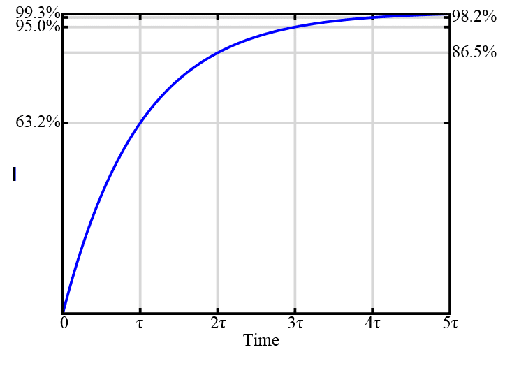
When using PWM for DC motor control this situation repeats during every period of PWM. If the load is only resistive, the PWM frequency has no effect, but in this RL circuit, the current rise is limited by inductance.
Therefore PWM signals using higher frequencies give less time for the current to rise.
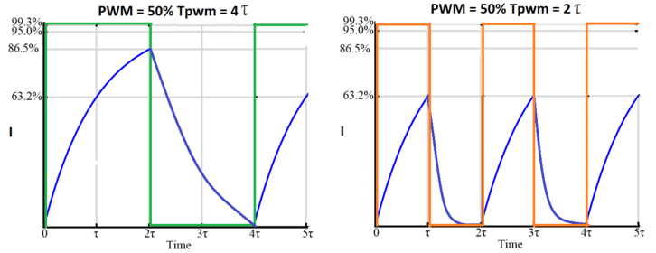
This means to simulate a linear response, the ‘on’ pulse time for the PWM should be greater than 5𝜏, i.e. 5×𝐿𝑅.
For example, if our motor has a time constant 𝜏=10𝜇𝑠, the minimum pulse width should be longer than 50𝜇𝑠.
If our minimal usable PWM duty cycle is 5%, then we should pick a frequency to ensure it is longer than 50𝜇𝑠. This gives a minimal PWM period of 20×50𝜇𝑠=1𝑚𝑠. A period of 1ms means our maximum frequency for linear response is 1 kHz, any lower and at low duty cycles, the current does not have enough time to reach close to its steady-state value.
Calculations For Precision Microdrives 110-003 Motor
Let’s try to calculate the maximum PWM frequency which gives a linear torque response with 1% PWM resolution. For this example we are using the 110-003 Micro Core™ DC motor, you can find its technical details in the datasheet (downloadable from the product page).
Rated voltage = 1.5V
Resistance = 3.4 Ω
Inductance = 19 µH
Time constant for this motor is:𝜏=𝐿𝑅𝜏=0.000019𝐻3.4Ω=0.0000056𝑠=5.6𝜇𝑠
Therefore the minimal pulse width should be longer than:5.6𝜇𝑠×5=28𝜇𝑠
With a minimum PWM resolution of 1%, the minimum pulse width is:28𝜇𝑠×100=2800𝜇𝑠
This determines the maximum frequency for linear response (remember this is where the inductance in the motor winding is not averaging the current to below the level that would provide the motor with maximum torque):10.0028𝑠=357𝐻𝑧
So i.e. if you want maximise the torque out of the motor, drive it with DC, or a PWM with frequency of less than 357Hz (in this example).
Testing With The Precision Microdrives 110-003 Motor
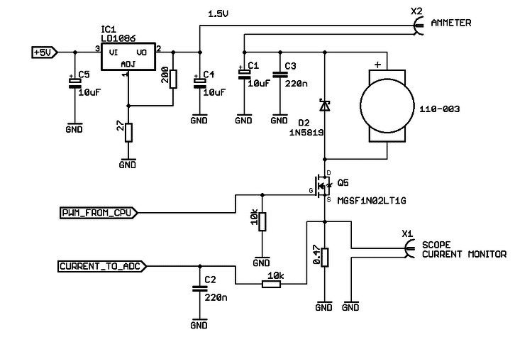
In the above testing circuit, the motor was controlled from a PWM source on an ATmega168 which was output through a MOSFET. An LDO voltage regulator (LD1086) made 1.5V available for the motor.
The current was measured between the voltage regulator and motor, and also between the transistor source and ground. The motor shaft was stopped, to simulate normal conditions where motor works with a load.
The three screenshots below are for three different PWM frequencies: 200 Hz, 2kHz and 31.25 kHz, but our minimum duty cycle is actually 10%. This means we should see linear behaviour at frequencies below 3.571 kHz (10 times the calculated minimum frequency at 1% duty cycle). We’re expecting that both the 200 Hz and 2 kHz signals to be similar and reach close to the expected DC current, but the 31.25 kHz signal will reach a significantly lower current.
The current value in the screenshots is the average current.
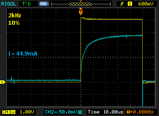
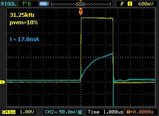
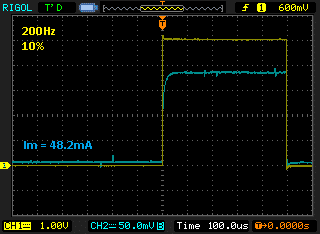
As we can see with 31.25 kHz, the current reaches close to 50% of the value for 2kHz. If the average current is less, this means the output torque is also less and is not a linear response.
At 2kHz the current reaches close to the maximum value (as with true DC control), so we can expect the frequency of 2 kHz to give a linear response above 10%. Similarly, with a 200Hz frequency, the peak current again reaches full value, as we expected with our calculations beforehand.
An important note is to analyse how the motor performs at lower frequencies. During our tests, we experienced some vibration and shaking on the motor shaft when powering at 200 Hz, so for a smoother drive system we would select a higher frequency.
The data and graph below make it easier to see the non-linear response at high frequencies. We’ve varied the duty cycle for the same 3 frequencies, a linear response should show a nice straight line between duty cycle and current draw. This means a change between 75% and 80% duty should yield the same change in torque (current draw) as 5% to 10%.
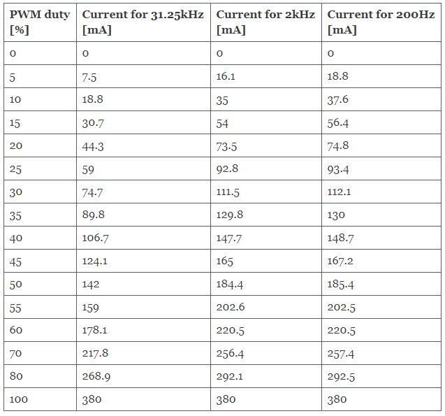
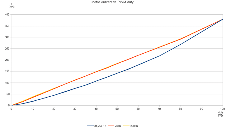
We can see that whilst the 200 Hz and 2 kHz frequencies don’t perfectly follow the theoretical ideal (it looks like there is a slight change in gradient above ~83%), the non-linearity is much more pronounced at 31.25 kHz.
It is important to find an acceptable balance between linear behaviour, noise, and unwanted vibration. For many applications, the non-linearity at higher frequencies will not be an issue, or the benefits of the higher frequency outweigh the drawbacks.
However if your application does require a high degree of linearity from a high-frequency PWM drive signal, you could consider the following to improve performance:
1. Switching the PWM frequency when the motor is starting, reducing the frequency can give a higher output torque. It can be done with most microcontrollers which have hardware PWM generator, usually with the phase-correct mode of operation
2. Increasing PWM resolution and making a lookup table in the code for motor response. We can vary the PWM to compensate for the motor’s non-linear response
3. Adding a current sensor and making a PWM closed-loop regulator to vary the frequency or duty cycle for linear response
All of these options require additional resources or coding if possible using a lower frequency PWM makes the design simpler.
Newsletter
Sign up to receive new blogs, case studies and resources – directly to your inbox.

Sign up
Discover more
Resources and guides
Discover our product application notes, design guides, news and case studies.
Case studies
Explore our collection of case studies, examples of our products in a range of applications.
Precision Microdrives
Whether you need a motor component, or a fully validated and tested complex mechanism – we’re here to help. Find out more about our company.