AB-029
Vibration Motors: Voltage vs Frequency vs Amplitude
Introduction
We’re often asked how to adjust the vibration amplitude or frequency of our various vibration motors. In this article, we’ll look at how simple it is, why it can be useful, and how we can predict the behaviour of a motor using the driving voltage and Typical Performance Characteristics graph.
There are two main types of vibration motors, eccentric rotating mass (ERM) and linear resonance actuators (LRA). LRAs require a very specific resonant frequency and an AC drive signal for optimal operation, so this article will focus only on ERMs.
Why Change Vibration Amplitude?
It is important to appreciate that while we can measure vibration amplitude in a controlled laboratory environment, the real-world perception of this vibration will vary due to a multitude of factors including (but not limited to):
- Rigidity or flexibility of the device
- Motor orientation
- Weight of the device
- User age
- Position of the device on the body
- Vibration frequency
- Environmental factors
Applications can have very different vibration amplitude requirements, a small wearable device for children will require a much lower vibration intensity than an industrial hopper.
Altering the vibration intensity also allows us to implement advanced haptic effects. This is a growing and exciting field, as it allows various embedded technology to communicate an increasing amount of information through vibration alone. By changing the intensity and pattern of vibration it is possible to create an essentially limitless number of combinations, rhythms or messages. The wearable and automotive fields, in particular, are seeing growing adoption of this technology.

Get in touch
Speak to a member of our team.
Motor catalogue
Looking for our products?
Reliable, cost-effective miniature mechanisms and motors that meet your application demands.
Why Change Vibration Frequency?
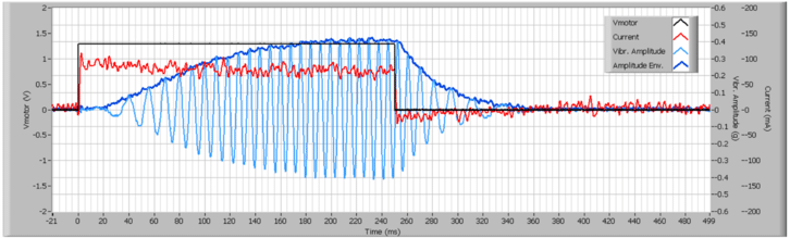
It is important to note that in ERMs the vibration amplitude and vibration frequency are inextricably linked. In the image above, the light blue line represents the measured vibration amplitude. The magnitude of the wave is the amplitude, but the period is the vibration frequency. Notice how as the magnitude increases, the period shortens (= increased frequency).
As you cannot alter one without altering the other, the most common reason the vibration frequency is changed is to change the amplitude. However, the vibration frequency also carries its own implications.
Just as the human ear perceives certain frequency sounds to be louder than others, vibrations are perceived slightly differently depending on their frequency. Different mechanoreceptors detect vibration at different frequencies, for example, the Pacinian Corpuscle is best at detecting vibrations in the 40 – 800 Hz range with its peak perception being between 200 and 300 Hz.
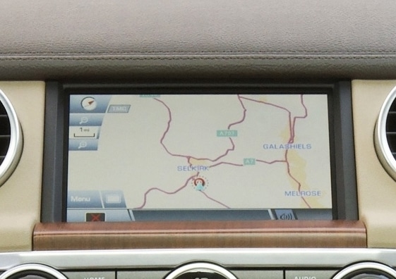
Automotive environments have many sources of vibration present, for example, the engine, road, air-conditioner and radio can all produce vibration at a range of frequencies. To prevent haptic feedback being lost amongst this noise it’s often necessary to use easily distinguishable frequencies.
A small subset of applications require a very specific frequency, perhaps it is necessary to induce a biological effect or there are certain mechanical requirements. Using rotary encoders, or back EMF measurement, we can develop a closed-loop control algorithm that maintains motor speed by adjusting the driving voltage as necessary. This ensures the speed remains within a tolerance tighter than the manufacturing specifications.
Another aspect, often overlooked, is the displacement that occurs as the motor vibrates. If we take two motors with the same vibration amplitude but different vibration frequencies the slower motor will produce more displacement. This can have a considerable effect on vibration perception. For example, we can use our Quick Vib Estimator (on the right-hand side) to calculate the displacement from two motors of similar amplitude – but with very different speeds.
Both the Uni Vibe™ 324-102 and the Uni Vibe™ 310-114 have Typical Normalised Amplitudes of 6 G, but the 324-102 is rated at 2,800 RPM and the 310-114 is rated at 12,000 RPM. Entering these details into the estimator with a target mass of 100g, we can see the 324-102 creates 0.684 mm of displacement whilst the 310-114 creates only 0.037 mm. These are only theoretical models, and the actual difference is very small, but comparatively speaking the 324-102 creates a much greater displacement that a user is likely to notice.
Effect Of Speed On Amplitude
In a rotational system, the relationship between motor speed and vibration amplitude is not linear but rather exponential, this is clearly shown in the following equation. It describes the force (centripetal) created by the rotating mass: 𝐹=𝑚𝑡𝑖𝑚𝑒𝑠𝑟𝑡𝑖𝑚𝑒𝑠𝑜𝑚𝑒𝑔𝑎2
Here, m is the mass of the eccentric load, r is it’s “eccentricity”, and the last item ω (omega) is the rotational speed in radians per second.
A nominal percentage increase in motor speed will result in a larger increase in amplitude, in theory, this means that we can affect considerable change by making relatively minor adjustments to the motor speed.
Modifying the ERM, in particular, its weight or eccentricity is another way to change the vibration intensity. However, this is obviously far less flexible as it is set during manufacturing and can’t be changed “on-the-fly”.
Link Between Speed And Frequency
For ERM vibration motors the motor speed and vibration frequency both represent the same thing.
Motor speed is simply a measurement of the revolutions per minute (RPM), while vibration frequency is expressed in Hertz (Hz) and is the number of vibrations per second. To convert from Hz to RPM we simply multiply by 60, as there are 60 seconds in every minute. Similarly, to convert from RPM to Hz we divide by 60.
How To Change The Speed
To control the motor speed we simply need to adjust the driving voltage. An increased voltage means the motor can output more torque, and because the load is fixed the speed increases.
For reliable and consistent motor operation the recommended driving voltage range is defined by two specifications. The minimum voltage to start the motor is defined by the Maximum Start Voltage. It may seem odd to use a Maximum value to define the minimum voltage, but it is for good reason. While it’s possible the motor may operate below this voltage, it is not guaranteed and the motor’s performance may be less than reliable.
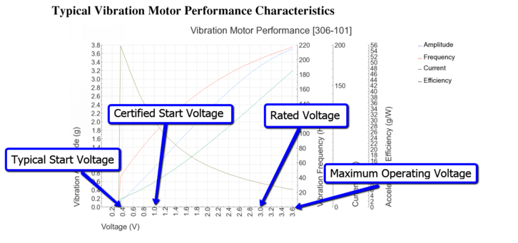
The upper voltage limit is the Maximum Rated Operating Voltage. It is important to avoid driving the motor beyond its maximum rated operating voltage as doing so can damage it. It is best not to exceed the Rated Voltage for a long period of time – values such as Maximum Operating Current may be inaccurate if driven above this value and the increased speed (and current) causes the brushes to wear quicker and the motor’s lifespan is reduced. Both of these specifications and more can be found on the relevant product data sheets.
Depending on your circuit and application there are many ways to alter the applied voltage, however, the most common method is by using PWM control. Other methods include using a basic linear voltage divider or special motor drivers. In fact, some drivers such as the DRV2605 hold libraries of waveforms, e.g. ‘clicks’ and ‘ramp-ups’, which will automatically handle the drive voltage for you. Interestingly, when using a battery as an unregulated power source you will typically see the driving voltage decrease as the battery discharges – which then results in a drop in speed.
Changing the speed of a Brushless DC vibration motor will depend on the driver being used. For example, the 910-101 has an integrated driver that accepts a varying voltage – but does not work with PWM. Conversely, the M10-400 evaluation board uses the DRV11873 driver which does accept a PWM signal.
Haptic driving techniques
Adjusting the driving voltage will not only affect the motor’s ultimate speed but also how quickly it gets there. This enters the world of haptic feedback and the special driving techniques designed to make vibration effects feel ‘crisper’. If you’re not using effects such as ‘clicks’ or ‘pulsing’ to communicate information to the user, you may wish to skip this section.
With the applied voltage ultimately determining the output power of the motor, we know that a higher voltage will cause the motor to turn at a higher speed. It follows that a higher voltage will also cause the motor to start more quickly because it has more power to overcome the inertia of the eccentric mass.
The technique of ‘Overdrive’ applies a higher voltage than the Rated Voltage to give the motor some extra power and start quicker – before quickly dropping to the Rated Voltage so the motor isn’t damaged. An ideal haptic device would have no lag and instantly start vibrating at the desired amplitude (according to the voltage applied).
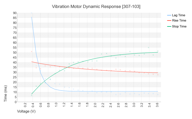
The graph above shows how long the motor takes to start and stop. Lag Time represents how quickly the vibration motor gets to 0.08 G, Rise Time is from start to 50% of the typical amplitude for the given voltage, and Stop Time is how long the motor takes to stop from running at the given voltage.
When we increase the driving voltage there is a very clear drop in the Lag and Rise Times, but similarly, there is an increase in Stop Time due to the increased momentum of the mass. ‘Active Braking’ is the opposite of Overdrive, where the polarity of the driving voltage is inverted. This causes the motor to drive in the opposite direction, effectively acting as a ‘brake’. Decreasing the Stop Time is an important part of getting that clear haptic effect.
See more about his topic in the improve haptic performance section of our haptic feedback content.
Difficulties In Predicting The Vibration Amplitude And Frequency
As with most theoretical models, there can be problems when trying to predict the real vibration amplitude based on a change in voltage. In this instance, there are three main reasons why the measured value of amplitude may vary from our estimation.
Non-Linear Voltage / Speed Behaviour
Doubling the voltage does not necessarily double the speed. Some motors have a high start voltage and very flat voltage/speed relationship, whilst others have very low start voltage but may not have a linear relationship.
In general, predicting the speed involves further equations and knowledge of the DC motor’s constants – which is beyond the scope of this Application Bulletin. In addition, it is not usually required as the motor’s performance across a range of voltages can be read from our datasheets (discussed below).
Manufacturing Tolerance
Even with access to the information above (motor constants etc), there are tolerances in the manufacturing of motors and two motors from the same batch may not behave exactly alike. Between batches, the difference may be even greater.
Notice in the Operational Specification section of the datasheets, the Rated Speed has a tolerance value attached. As we’ve described above, a change in speed has a created impact on the vibration amplitude.
Measurement Inaccuracies
The equations above are based upon a simplified model, using limited degrees of freedom. In reality, the vibration motor has multiple modes of vibration at different speeds/amplitudes and there are also considerations for the mounting material and technique (particularly referring to the rigidity).
So whilst they are useful in explaining the theory of how voltage affects the speed and amplitude, they cannot be used for extremely accurate predictions. They can, however, be used for general estimates if required.
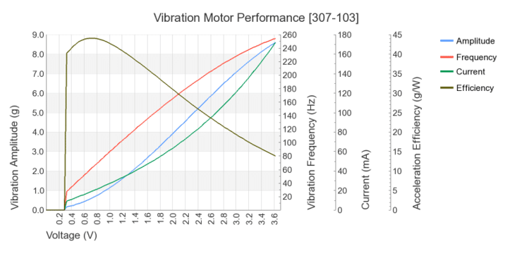
Thankfully, you don’t need to calculate the vibration amplitude or vibration frequency for our ERM motors – we’ve already done the work for you. Our datasheets include Typical Performance Characteristics graphs that show a sweeping voltage plotted against vibration amplitude, frequency, efficiency, and the current draw.
The graph below is for the 307-103, where we can see the (slightly) non-linear voltage/frequency relationship, and a much more pronounced non-linearity with the vibration amplitude:
Customised Motors
Of course, changing the driving voltage is not the only way to modify motor speed or vibration amplitude, there are two general areas of customisation that would affect the motor’s performance.
We have previously discussed the process of designing customised eccentric masses, and their impact on performance, in Application Bulletin 027: Eccentric Mass Parameters for Vibration Motors. Essentially, the design of the mass can affect the load seen by the DC motor and therefore affect the voltage/speed relationship of the motor.
Also, it is possible to provide DC motors with custom electrical and/or mechanical characteristics, such as rewinding them for a different Rated Voltage. DC motors also come in a variety of form factors, which can limit certain design choices. For example, the 308-103 can afford to have an oversized eccentric mass for additional amplitude – but this is not possible for encapsulated or coin vibration motors.
Both of these customisations enable the creation of different profiles for balancing motor size, speed, voltage, and load – the combination of which gives us our different vibration motor products tailored for different applications.
Conclusion
We can readily manipulate the driving voltage to adjust motor speed and in turn, alter the amplitude and frequency of vibration. We have also explained that vibration amplitude and frequency are linked and cannot be controlled independently by the voltage, because they are both dependant upon the speed.
We have seen that the relationship between vibration amplitude and frequency (and therefore speed) is not linear, and we’ve also shown it can be difficult to predict the real world amplitude from a change in voltage. However, Precision Microdrives’ Typical Performance Characteristics graphs greatly simplify this process and enable you to read the motors (typical) behaviour at a given voltage.
In addition, altering the voltage can have an effect on how quickly the motor starts to turn – not just it’s ultimate speed. For this reason, it is possible to use the voltage to improve haptic effects and motor performance.
By ensuring that the driving voltage is between the Maximum Start Voltage and the Maximum Rated Operating Voltage we can ensure the longevity and reliability of the motor. To help select the correct motor you might find our Vibration Motor Comparison Guide useful.
Newsletter
Sign up to receive new blogs, case studies and resources – directly to your inbox.

Sign up
Discover more
Resources and guides
Discover our product application notes, design guides, news and case studies.
Case studies
Explore our collection of case studies, examples of our products in a range of applications.
Precision Microdrives
Whether you need a motor component, or a fully validated and tested complex mechanism – we’re here to help. Find out more about our company.