AB-030
Extending Vibration Theory – Displacement And Dissipation
Introduction
This application bulletin looks to extend our previous work on the characteristics of vibrations using eccentric rotating mass vibration motors. Based upon the theoretical content found at the end of our product datasheets, we take a closer look at what dictates the magnitude of displacement, the energy dissipated in each cycle, and the resulting design implications.
This means that most of our discussion builds on our previous understanding of vibration amplitude and frequency. These factors are simply referenced in the material below, to read about them in detail we would recommend the following resources:
- VAB-02: How Do Vibration Motors Work? (04:16 min, quickest and easiest overview)
- VAB-03: How Do LRAs Work? (04:58 min)
- AB-004: Understanding ERM Vibration Motor Characteristics
- AB-020: Understanding Linear Resonant Actuator Characteristics
- AB-029: Vibration Motors – Voltage vs Frequency vs Amplitude
Although much of the theory specifically refers to ERMs, the resulting conclusions also apply to linear resonant actuators. In particular, we discuss how material rigidity affects displacement and current draw – which applies equally well to ERMs, LRAs, and any other source of vibrations.

Get in touch
Speak to a member of our team.
Motor catalogue
Looking for our products?
Reliable, cost-effective miniature mechanisms and motors that meet your application demands.
Quick Overview Of ERM Vibration Formulae
The following formulae act as the basis for our discussion of displacement and energy dissipation. They are covered in full in the Application Bulletins mentioned above – rather than repeating ourselves here, we will simply highlight them for reference.
The vibration amplitude is a unit of acceleration, from Newton’s second law of motion:𝐹=𝑀×𝑎
Where 𝑀 is the target mass (i.e. the object the motor is attached to), 𝑎 is the acceleration in meters per second (vibration amplitude is normally in g), and 𝐹 is the force created by the rotation of the motor:𝐹=𝑚×𝑟×𝜔2
Here, 𝑚 refers to the eccentric mass on the motor (not to be confused with capital 𝑀, the target mass), 𝑟 is the eccentricity of the mass and 𝜔 is the angular velocity.
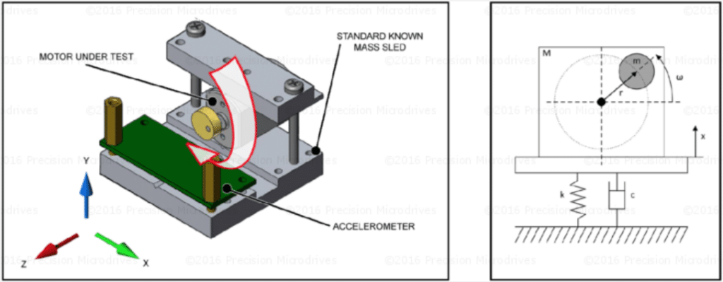
However, in order to analyse the displacement and energy dissipated from the ERM, we need to consider the full equation of motion for the system. For this we must also consider the properties of the target mass, as such we include a spring and damper to more accurately represent how the vibration motor and the target mass behave. The equation below describes the motion, which uses 𝑥 to represent the displacement:(𝑀–𝑚)𝑑2𝑥𝑑𝑡2+𝑐𝑑𝑥𝑑𝑡+𝑘𝑥=𝐹0sin(𝜔𝑡)
This equation is important because it considers the stiffness 𝑘 and damping 𝑐 of the target mass, whereas previous equations (such as in VAB-02) used a more simplified model and assume perfect transmissibility between a motor and target mass.
If you’re interested in the derivation of the above equation, see AB-004: Understanding ERM Characteristics. We will use the equation as a basis for discussing how a target mass responds to the force generated by an ERM.
Resonant Frequencies, Damping, And Loss Factors
Before diving into the displacement and energy dissipation, we should cover some basic terms. The key foundation for the discussion is interpreting an ERM attached to a target mass (i.e. the object, PCB, enclosure, etc) as a single degree of freedom (DOF) system.
This is best explained in the image below. On the right-hand side, we see an equivalent system that includes the spring (k) to represent the stiffness and a damper (c) that we mentioned in the equation above. These help to describe the energy loss. Using this model helps us explain the impact of material stiffness, damping, and the system’s resonance.
Mechanical resonance is a physical phenomenon where an external force (such as the force produced by the ERM) can drive a system to a much higher amplitude at a specific frequency. This is known as the Resonant Frequency, in most scenarios engineers are trying to reduce the effects of resonance as it can be catastrophic for large structures such as buildings and bridges. However, those familiar with LRAs will recognise that it can also be a desirable effect in vibration actuators. The figure below demonstrates how the vibration response peaks when the input frequency 𝜔 is equal to the ‘natural’ frequency of the system, 𝜔𝑛.
Stiffness is the easiest concept to understand and plays an important part in the resonant frequency. We can recognise that a metal object is ‘stiffer’ than, say, wool. Stiffer objects have higher resonant frequencies.
Damping should not be confused with stiffness, it refers to the losses that occur in the system throughout each cycle. There are generally three types of dampening that we are concerned with:
- Overdamped – the system decays with no oscillation
- Underdamped – the system oscillates but continues to decay
- Critically damped – the system returns to zero as quickly as possible, with no decay
Tuning forks are a great example of visualising resonance, stiffness, and damping. When struck, they vibrate at their resonant frequency, which depends on their stiffness, and they ring for a long time as they are underdamped.
You don’t need a deep understanding of resonance or damping, we will explain the pertinent bits as needed. For now, it is simply enough to accept that the vibration response of a system is not linear across all frequencies, energy is lost in each cycle, and both are affected by the type of material.
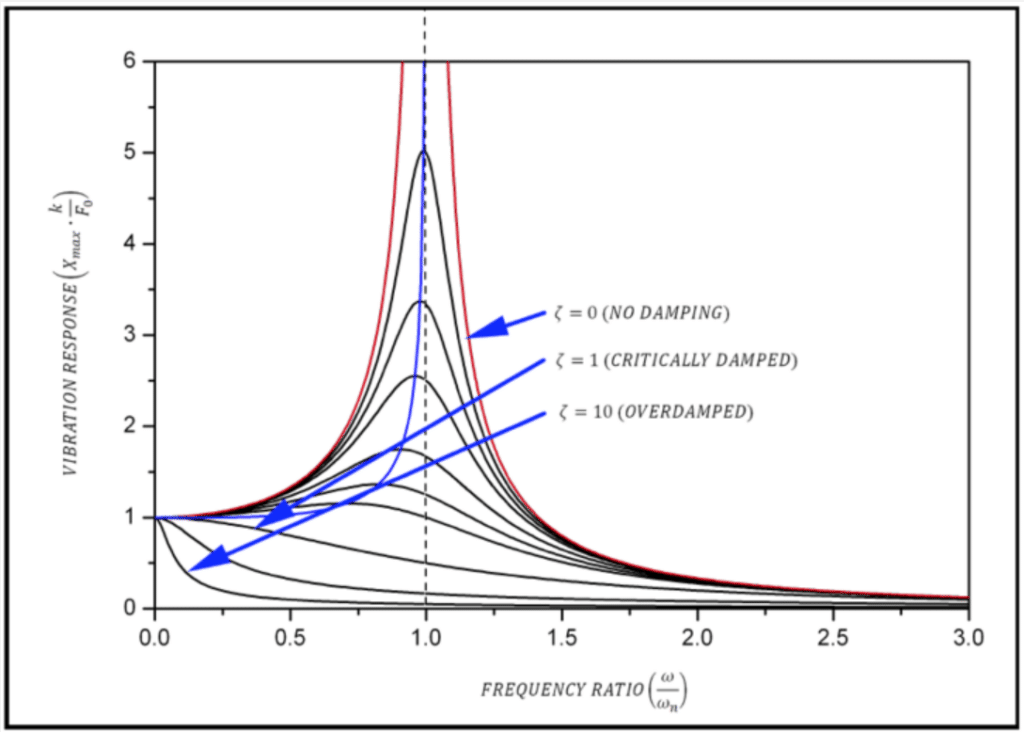
As a brief note on our testing procedures, we carefully design our test sleds to produce representative values by reducing the effects of resonance. It would be disingenuous to claim our motors possessed a particularly high vibration amplitude, which only occurred near the resonant frequency. For example, we can see that the vibration response can be extremely high around the resonant frequency (especially with a low damping factor).
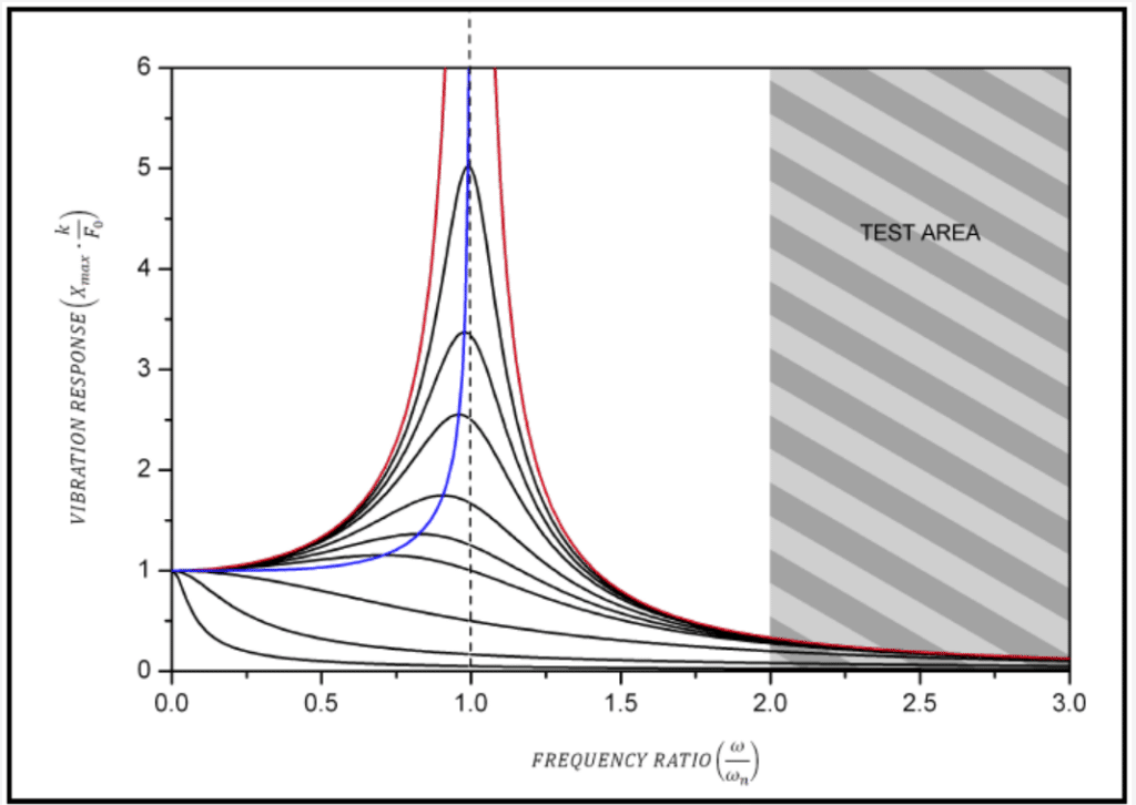
Therefore, our motors are tested in machines with very low resonant frequencies, much lower than the test frequency. This enables a similar vibration response across different damping ratios (although typical vibration applications are often underdamped, as discussed later) and drastically reduces the impact of resonance. In this discussion, we simply need to recognise its existence in order to understand displacement and energy dissipation.
Displacement Resulting From ERMs
In a steady-state condition, the displacement amplitude can be approximated with the following formula:𝑋𝑚𝑎𝑥=𝐹𝑘1[1−(𝜔𝜔𝑛)2]+[2𝜁(𝜔𝜔𝑛)]2‾‾‾‾‾‾‾‾‾‾‾‾‾‾‾‾‾‾‾‾‾‾√
Where:
| 𝑋 is displacement | 𝐹 is the ERM’s force | 𝑘 is the stiffness (spring constant) |
| 𝜔 is the ERM’s angular frequency | 𝜔𝑛 is the resonant frequency | 𝜁 is the damping ratio |
From this equation, we can see several things that you might consider obvious:
- The greater the motor force, the greater the displacement
- The stiffer the system, the smaller the displacement
- The displacement is greatest when the ERM’s frequency is equal to the system’s resonant frequency
Point 2 raises an important note about the dangers of over-simplifying models. You might consider that, desiring the largest displacement possible, it would be advantageous to mount the motor to something flexible in order to reduce the stiffness. However, you must consider how the motor’s mounting fits within your application.
For example, imagine an SMD type ERM soldered to a PCB within a handheld device. If the device PCB is flexible (low stiffness), then the displacement from the motor’s force occurs on the PCB and is not transferred to the outer casing. Being a handheld device, this would actually reduce the vibration strength perceived by the user. Therefore, it is actually more beneficial to have a mounting object that is very stiff and secured to the motor such that the motor and its target mass move in unison. Similarly, in this example, it would be beneficial for the casing of the device to be equally stiff, such that all the motor’s force enacts on the unit as a whole.
It’s important to note that the equation above is not inaccurate, simply that we must be careful where we draw the bounds of our system. We want as much of the displacement to occur at the point of interaction with the user. Everything else in between would ideally be as stiff as possible.
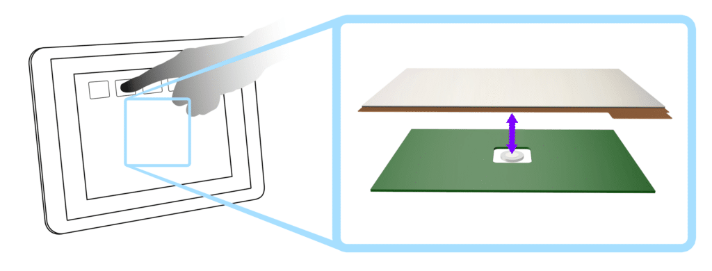
This concept is sometimes referred to as mechanical isolation. A great example is a touchscreen panel on a car dashboard. We neither want the displacement to occur on the underlying PCB nor do we want to attempt to vibrate the entire dashboard. Instead, everything between the vibration motor and the interface panel is kept as rigid as possible, but the panel itself might either be flexible or it may be separated from the surrounding dashboard with a softer rubber – enabling it to move independently.
In general, you should aim to allow minimal flexibility between the source of vibration (the ERM) and the recipient (e.g. a user’s finger/hand) to maximise displacement for the user.
As a final note, you should be aware that the damping ratio is dependant upon the stiffness, as seen through the following equation:𝜁=𝑐2𝑚𝑘‾‾‾√
You might have initially inferred that an increased damping ratio would lead to a reduced displacement, however, you can see that this would actually be the result of a decreased stiffness (assuming a constant mass and damping coefficient ) – which is consistent with the discussion above.
Energy Dissipation
We know that practically speaking no system we design will be completely rigid. All materials have some level of flexibility, resulting in a loss of energy in each cycle.
Again, this plays into the point above regarding system boundaries. The energy isn’t really ‘lost’, it is transferred into a different form of energy outside of our system. Of course, this is the entire point of our vibration motor, we want it to transfer kinetic energy to the target mass. So again we stress the point of considering the correct system boundary for your application.
Based on an idealised viscous damping model, the energy dissipated per cycle 𝑊𝑑 is given:𝑊𝑑=𝜂𝜋𝑘𝑋2
Where 𝜂 is the damping loss factor, and equal to 2×𝜁. As the damping is expressed as a loss, a flexible material will have a higher value than stiff metals. The table below shows some typical values:
| Material | Approximate Loss Factor |
| Metals | <0.001 |
| ABS | 0.01-0.02 |
| PA | 0.03 |
| Neoprene | 0.1 |
| Butyl Rubber | 0.4 |
Using the equation above and referring to the table of loss factors, we can see that a motor mounted to ABS would have a lower energy loss than neoprene. This extra energy dissipation is balanced from the excitation energy from the ERM. We can conclude that a motor clamped to a hard surface with little movement requires less input power than a motor on a soft material (e.g. held in your hand).
We can also see the above loss factors are relatively low, in fact, damping ratios ( 𝜁) of vibration-isolated systems typically vary from 0.05 to 0.3, meaning that systems are often underdamped.
Design Implications And Conclusion
With applications that involve human users, such as haptic feedback, the equations above for displacement and energy dissipation might seem overly complicated. In fact, when considering vibration amplitude and frequency, the discussion in VAB-02 should be sufficient.
However, they are great for highlighting two critical points for your design:
- First, a flexible material will displace more and dampen quicker than a stiff object. As a result, vibration motors draw less current when mounted to a rigid object.
- Second, we must carefully consider where our system boundaries are. For example, we generally want our energy dissipation to occur at the point of contact with the user. This is achieved by keeping the parts between the ERM and user as rigid as possible, you may also wish to consider mechanical isolation.
It should also be noted that when it comes to discussing the resulting vibration ‘strength’, there are many other factors that impact upon how humans perceive the vibrations. The displacement described above is only one factor in characterising the vibration, in addition to amplitude and frequency. For example, different areas of the body are more sensitive than others – and there are even different types of receptors which excite in different frequency ranges. Specific applications will range, in terms of rigidity/flexibility, motor rotation and position, target mass, and other environmental factors. Extensive testing is the best way to help maximise the results of your calculations and design.
Newsletter
Sign up to receive new blogs, case studies and resources – directly to your inbox.

Sign up
Discover more
Resources and guides
Discover our product application notes, design guides, news and case studies.
Case studies
Explore our collection of case studies, examples of our products in a range of applications.
Precision Microdrives
Whether you need a motor component, or a fully validated and tested complex mechanism – we’re here to help. Find out more about our company.