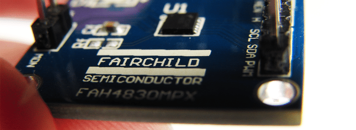
Fairchild Semiconductor’s FAH4830
Fairchild Semiconductor recently released the FAH4830 haptic driver for DC vibration motors and Linear Resonant Actuators, we’ve had the opportunity to work with it in-house with our actuators.
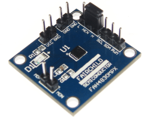
Aimed at mobile phones and handheld devices the chip has a low standby current (under 500 nA) and a small 10 lead MLP package. For anyone who has attempted to prototype with tiny ICs before, you will be glad to know there is also an evaluation board that gives access to all of the pins through headers. See this page for the application note on the FEBFAH4830 evaluation board, much simpler!
By default, the FAH4830 produces a DC output voltage for ERM vibration motors. The chip is controlled by an external PWM signal where the duty cycle sets both the vibration amplitude and the rotation direction. For example, 90% duty cycle is maximum vibration amplitude in one direction, with 10% being maximum amplitude in the other direction. At 50% the positive and negative outputs to the motor are equal, resulting in no voltage drop across the motor.
Of course, in a device we humans are not very good at feeling which direction the motor rotates, so you may ask why this is an important feature. Well, it enables techniques like Active Braking, where reversing the voltage quickly stops the motor for a crisp haptic effect. Also, it can improve effects like a ‘double-click’ as you can take the motor from maximum vibration amplitude in one direction to the other maximum vibration amplitude without stopping in the middle, again improving the user experience.
Other advanced features such as Overdrive can be enabled by writing to the onboard control registers via the I2C communication pins. With headers in place for all the necessary connections and an on-hand Arduino Uno, we were able to get both our ERMs and LRAs up and running very quickly:
As an example, to get up and running with the C10-100 (resonant frequency 175 Hz) change the register CONTROL0 (address 0x20) to the following:
| Bit # | 7 | 6 | 5 | 4 | 3:2 | 1:0 |
| Value | 1 | 0 | 0 | 0 | 00 | 01 |
| Description | Normal operation mode | Overdrive disabled | Overdrive low | LRA mode | Not used | 1/128 PWM divider |
hat’s 0x81, B10000001, or 129 in decimal. With the PWM divider set at 128, to ensure the correct resonant frequency of 175 Hz we need a PWM frequency of (128*175) 22,400 Hz. As the Arduino default PWM frequency is ~490 Hz you will need to change it in the code. You can edit the registry to enable/disable other features and drive ERMs.
Look out for this chip in an upcoming section of our website that will act as a resource for all types of drivers and chips that we will recommend for use with our gearmotors, vibration motors, brushless vibration motors, and LRAs.

Get in touch
Speak to a member of our team.
Motor catalogue
Looking for our products?
Reliable, cost-effective miniature mechanisms and motors that meet your application demands.
Newsletter
Sign up to receive new blogs, case studies and resources – directly to your inbox.

Sign up
Discover more
Resources and guides
Discover our product application notes, design guides, news and case studies.
Case studies
Explore our collection of case studies, examples of our products in a range of applications.
Precision Microdrives
Whether you need a motor component, or a fully validated and tested complex mechanism – we’re here to help. Find out more about our company.