AB-026
Sensorless Speed Stabiliser For A DC Motor
Introduction
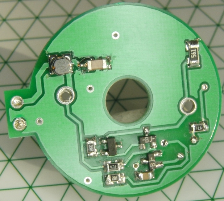
Motor speed is a parameter of a DC motor that is often measured and controlled, usually through additional sensors and with closed loop feedback. This method of speed control requires some form of speed sensor, normally mounted on the motor shaft. Some of our DC motors and gear motors have rear shafts for just this purpose, like the 212-109.

This block diagram is a typical closed loop control system, which can be designed either to operate analogue or digitally.
Hall sensors and Opto sensors are commonly used with digital controllers, whilst analogue circuits often use tacho-generators. With PWM control it is possible to achieve good accuracy, flexibility, and reduce power losses. However, this comes at the cost of an additional component and potentially a mechanical design modification if you’re planning to use it in an existing product.
For brushed DC motors it’s possible to measure and control speed without any sensors on the motor, exploiting a basic characteristic – speed dependant back EMF voltage.
Sensor-less Analogue Motor Speed Measurement
A DC motor is modelled as a serial connection of internal resistance and back EMF voltage source. The voltage on motor terminals is the sum of back EMF and the voltage dropped over the coil resistance.

Get in touch
Speak to a member of our team.
Motor catalogue
Looking for our products?
Reliable, cost-effective miniature mechanisms and motors that meet your application demands.
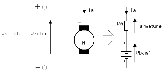
The voltage drop on the internal armature resistance is dependent on the motor current (and therefore on the load torque). It is impossible to measure speed directly by only measuring the voltage on the motor terminals.
The winding resistance Ra is generally constant – although it has a small temperature dependence, we can compensate for it to ensure the voltage drop on the motor armature is proportional to motor current.
As it is not possible to measure the back EMF directly, we need to calculate it from this equation: 𝑉𝑚𝑜𝑡𝑜𝑟=𝑉𝑏𝑒𝑚𝑓+(𝐼𝑎×𝑅𝑎)
Unfortunately, it is not possible to measure the armature voltage directly either – however, we can connect an additional (external) resistor in series with the motor. Measuring the voltage drop on this series resistor enables us to determine the back EMF.
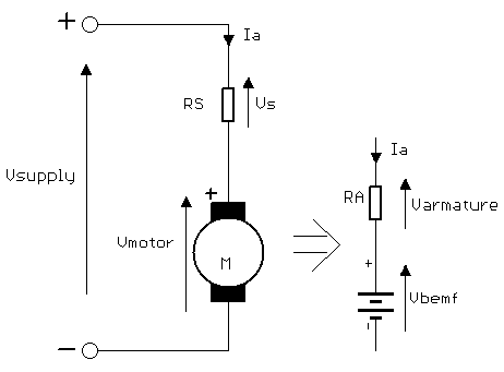
If we set the value of the series resistor to be equal to the resistance in the motor, we ensure any change in the voltage drop across the series resistor is equal to the voltage drop in the armature:𝑉𝑎=𝐼𝑎×𝑅𝑎𝑉𝑠=𝐼𝑎×𝑅𝑠𝑅𝑠=𝑅𝑎𝑉𝑠=𝑉𝑎
So we first need to know or measure the motor’s armature resistance. This can be done by measuring the resistance across the motor’s terminals using an ohmmeter, or by measuring the stall current with a known supply voltage. If using the latter, it is preferable to use a low supply voltage to avoid overcurrent damage.
For example, when supplying the motor with 1.2 V and measuring 100 mA during stall the armature resistance is calculated as:𝑉𝑠𝑢𝑝𝑝𝑙𝑦=𝐼𝑠𝑡𝑎𝑙𝑙×𝑅𝑎𝑅𝑎=𝑉𝑠𝑢𝑝𝑝𝑙𝑦𝐼𝑠𝑡𝑎𝑙𝑙𝑅𝑎=1.2𝑉100𝑚𝐴𝑅𝑎=12Ω
When using the ohmmeter for terminal resistance measurements, take an average of several readings at different rotor positions.
The supply voltage will be equal to the series resistor voltage, armature resistance voltage, and back EMF voltage.𝑉𝑠𝑢𝑝𝑝𝑙𝑦=𝑉𝑠+𝑉𝑎+𝑉𝑏𝑒𝑚𝑓
We can calculate the back EMF voltage by subtracting double the voltage drop on the series resistor from the supply voltage.𝑉𝑏𝑒𝑚𝑓=𝑉𝑠𝑢𝑝𝑝𝑙𝑦–(2×𝑉𝑠)
To reduce power losses we can use a lower value series resistance, but the resistor will ultimately decrease the voltage seen by the motor. Using a bridge circuit we can preserve the high measurement sensitivity and compensate the power loss in the motor:
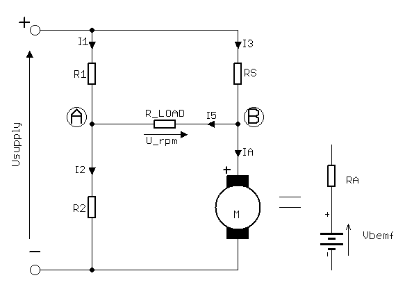
The right-hand leg of the bridge consists of the motor M and resistor Rs in series. The left-hand leg is a series connection of resistors R1 and R2, each leg is connected to power supply. The back EMF voltage is measured between points A and B.
Rload represents the input resistance of our measuring circuit. As this will consist of an op-amp, its input resistance will be much greater than other resistances in this circuit (ideal op-amps have infinite input impedance).
We need to ensure that the voltage between points A and B is independent of the motor current and supply voltage and that it is only dependant on motor speed and the input resistance of measuring circuit (Rload).
We start by analysing the circuit without any back EMF, i.e. when the motor is in stall condition. For the bridge to be balanced, the voltage between points A and B should be zero. This occurs as long as the ratio between R1 andR2 is the same as Rs and Ra:𝑅2𝑅1=𝑅𝑎𝑅𝑠
h is gain factor of our bridge:ℎ=𝑅1𝑅2=𝑅𝑠𝑅𝑎
If we release the motor from its stall condition, the back EMF voltage is proportional to speed:𝑉𝑏𝑒𝑚𝑓=𝑘𝑒×𝑛
where ke is the electrical constant for our motor and n is motor speed.
If the motor is allowed to rotate at the no-load speed, for an ideal motor we expect that Ia is equal to 0. This is because ideal motors ignore air drag and bearing friction. The voltage at the no load speed is:𝑉𝑟𝑝𝑚𝑁𝐿=𝑘𝑒×𝑛𝑁𝐿
From this, Vbemf can be signed as:𝑉𝑏𝑒𝑚𝑓=𝑉𝑟𝑝𝑚𝑁𝐿×𝑛𝑛𝑁𝐿=𝑉𝑟𝑝𝑚𝑁𝐿×𝐾
Where K is proportional factor between Vbemf and V_rpm in our circuit.
Now we can make a system of equations for our circuit:
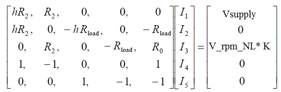
Solving for I5:𝐼5=ℎ(ℎ+1)𝑉𝑟𝑝𝑚𝑁𝐿×𝐾2ℎ(𝑅𝑎+𝑅2)+(ℎ+1)2×𝑅𝑙𝑜𝑎𝑑
So the output voltage is equal to:𝑉𝑟𝑝𝑚=𝐼5×𝑅𝑙𝑜𝑎𝑑=ℎ(ℎ+1)×𝑉𝑟𝑝𝑚𝑁𝐿×𝐾2ℎ(𝑅𝑎+𝑅2)+(ℎ+1)2×𝑅𝑙𝑜𝑎𝑑×𝑅𝑙𝑜𝑎𝑑
And for no load operation:𝑉𝑟𝑝𝑚=ℎℎ+1×𝑉𝑟𝑝𝑚𝑁𝐿×𝐾
The output voltage between points A and B is independent from power supply and motor current, both with no load and in loaded operation. It is dependent on h, and when increased the output voltage is also increased.
As mentioned previously, the armature resistance will change with temperature – unbalancing the bridge and affecting the output Vrpm. The bridge should be tuned with the motor is at operating temperature to minimise this effect.
This method of speed stabilisation was a popular solution for governor rotor speed controllers found in tape recorders using analogue electronics. In the era of the tape recorder, many companies made chips for DC motor control to ensure the tape moved at a constant speed. This was an interesting solution because it operated linearly and didn’t produce any noise, like PWM based controllers.
Common ICs included the LA5586, TDA7274, BA6220, and AN6550. Unfortunately, most of these have been discontinued and are now only available from aftermarket sources. The circuits in the ICs were slightly different, but the principle of operation is still based on the bridge circuit above.
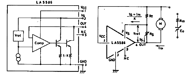
Note the equivalent circuit is drawn with current sources and a constant current ratio. The current ratio is between 20 to 40, depending on the specific IC, and is marked as K. In integrated circuits it’s easy to make two current sources with the same temperature parameters.
The motor is connected in one bridge leg, and the second leg contains a resistor with a value K times greater than internal motor resistance.
In steady state, the motor current is K times greater than the current through Rt. The negative input of the op-amp is connected to the voltage source, so the voltage drop on resistor Rt will always be lower than the motor voltage. The difference will equal Vref. The voltage in point A (with reference to ground) will always be higher than the voltage in point B.
Without Rs, the current through Rt is 40 times less than motor current. When the motor load increases, the voltage at point B increases, and the amplifier output voltage also increases. A higher amplifier voltage causes a higher motor current, which increases motor torque. Speed regulation can be achieved by adding shunt resistor – the voltage between points A and B is always equal to the reference voltage, so it’s easy to control additional current added to Rt.
This circuit will be balanced when the motor voltage is equal to the sum of voltages across Rt and Rs (Vref). The steady state equation is:𝐼𝑚×𝑅𝑚+𝑉𝑏𝑒𝑚𝑓=𝑅𝑇×𝐼𝑠+𝑅𝑇×𝐼𝑠+𝐼𝑚𝐾+𝑉𝑟𝑒𝑓
From this, the equation for back EMF is :𝑉𝑏𝑒𝑚𝑓=𝑉𝑟𝑒𝑓+(1+1𝐾)×𝑅𝑇×𝐼𝑠+𝑅𝑇𝐾–𝑅𝑚×𝐼𝑚
Assuming:𝐾×𝑅𝑚=𝑅𝑇
then the number of revolutions determined by Vbemf are:𝑉𝑏𝑒𝑚𝑓=𝑉𝑟𝑒𝑓+𝑅𝑇×(1+1𝐾)×𝐼𝑠
It is Important that in all cases Rt should be less than K x Rm otherwise the circuit will be overcompensated and unstable.
Analogue Speed Controller With Negative Resistance
Increasing the load on the motor causes the current draw to increase and the speed to drop. The back EMF and the voltage across the motor also decreases, this method of control is known as Negative Terminal Regulator.
In this case, we use an op-amp to control the speed, so our R_load will be thousands greater than other resistance in this circuit and can again be omitted.
From the previous section, we know that the power supply voltage didn’t change Vrpm, allowing us to power-up our circuit from a hi-power op-amp or add a transistor to the output of a standard op-amp. Connecting the inverting input to the bridge leg, between the motor and series resistor, we can control the bridge power supply by voltage connected to the non-inverting output.
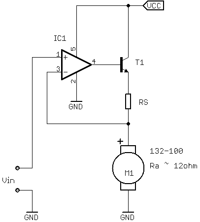
The input voltage is applied to the non-inverting input of the op-amp, and an inverting input is connected directly to the motor terminal. We cannot control the speed with the circuit yet, in this connection our amplifier works as a buffer (or voltage follower) with a gain equal to 1. Essentially, the input voltage defines motor voltage.
It’s possible to change the speed of the motor by setting the voltage Vin, but this doesn’t keep a constant speed when the load varies. For a constant input voltage, the motor will turn faster with light loads, and slow as the load is increased. We need a few more components to stabilise the motor speed.
The voltage drop on Rs is proportional to the voltage drop on motor armature resistance, we will use this voltage to compensate the voltage drop on armature resistance. This can be done by adding modifying the circuit to the one below – adding R1 and R2 and connect their mid-point to the non-inverting input of the op-amp.
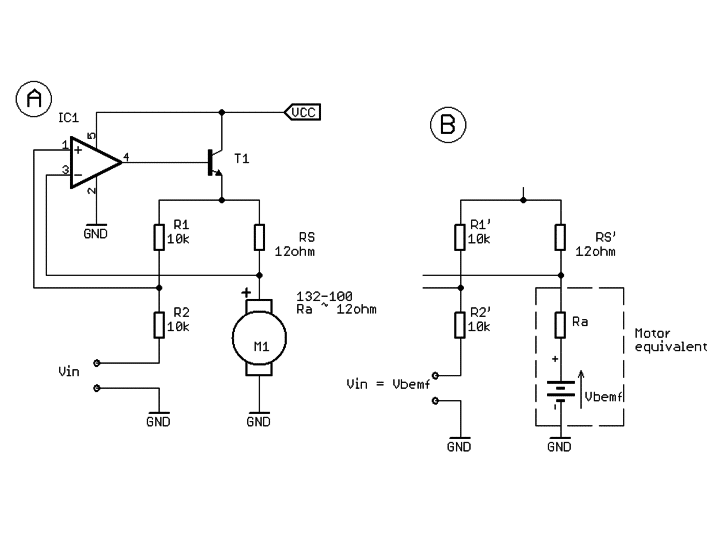
The ratio of R1 and R2 should be the same as Rs and Ra to ensure speed stabilisation. The image above shows the complete circuit and its equivalent for guidance, the control voltage should be the same as the back EMF voltage at the desired speed.
The compensation factor is defined by the value of Rs but it is more convenient to use a standard resistance value, then changing R1 or R2 accordingly.
If the motor speed decreases when a load is applied, the R2 value should be increased (or R1 should be decreased). If the motor speed starts to oscillate (or tends to increase) when a load is applied, R2 should be decreased or (R1should be increased).
In order to design this circuit, we need to know what the value of the back EMF at the desired speed:
- To find the back EMF voltage at the desired speed, the motor shaft can be mounted to and driven by a driller. Once at the desired speed (checked with a tachometer) measure the voltage on motor terminals using high impedance voltmeter.
- Measure the internal resistance of winding using an ohmmeter on the motor terminals, it’s good to take an average from a few different rotor position measurements.
- Choose a value for Rs from standard values, it may be less than the motor resistance.
- Choose R1 and R2 so the ratio is the same as the ratio between Rs and Ra. The actual resistor values should be greater than Rs and Ra to save current. Because the equivalent resistance of the bridge legs will be different, the op-amp should be a low input current type.
- Apply a control voltage the same as desired back EMF.
- Check speed and compensate accordingly (outlined in the paragraph before this list).
For temperature compensation, it’s possible to choose Rs with the same temperature coefficient as motor windings – for copper, it’s 3400ppm. This resistor should be placed as close to the motor as possible to maintain the same temperature condition.
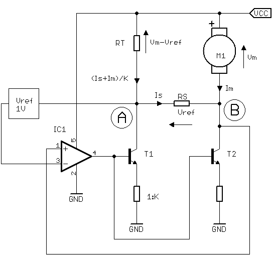
A simple motor speed stabilisation circuit can also be made with transistors only:
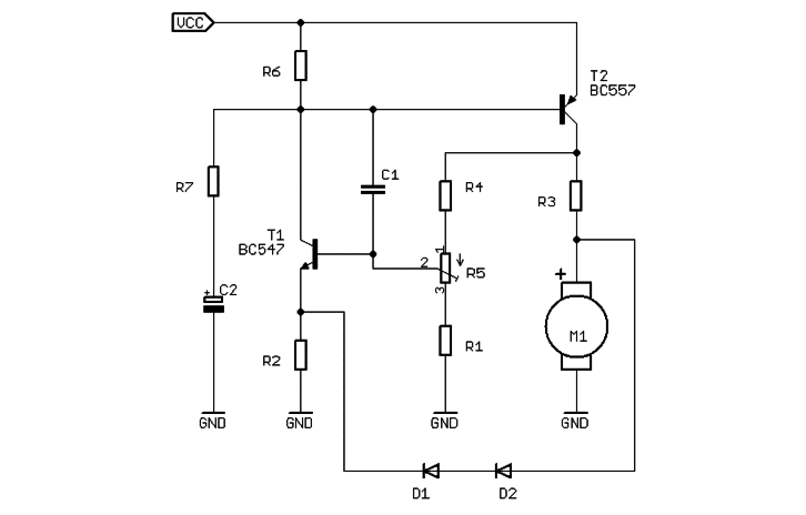
In this circuit T2 works as the output stage and T1 as an error amplifier. The signal on T1’s collector is an output signal, the emitter works as an inverting input and the base as a non-inverting input.
The voltage signal at the motor is connected to the non-inverting input because the output stage is inverting this signal, which means a greater signal on collector causes less motor current.
Diodes D1 and D2 make a reference voltage, the voltage on T1 emitter is always lower than the voltage on the motor terminals. Compensation voltage is taken from R3 and is subtracted from the bridge supply voltage which is measured by the voltage divider R4, R5 and R1.
R7 and C2 are a startup circuit to help overcome static friction, whilst C1 is a frequency compensation capacitor prevent for high-frequency oscillation.
As we need an accurate back EMF measurement, which is dependent on the contact resistance between commutator and brushes, it is best to use motors with metal brushes. Most of Precision Microdrives motors have metal brushes and are suitable for this method of speed control.
Speed Controller With Specialised IC
This circuit is based on AN6651, a specialised motor controller that was previously popular in tape recorders.
The AN6651 operates on the same principle as the LA5586 described above. Pins 2 and 4 are current source outputs, ratio between the control output (pin 2) and motor output (pin 4) is 40:1.
The resistance R1, connected between pin 2 and the power supply, should be 40 times greater than internal motor resistance for the same voltage drop on R1 as on motor internal resistance:𝐾=40𝑅1=𝐾×𝑅𝑚
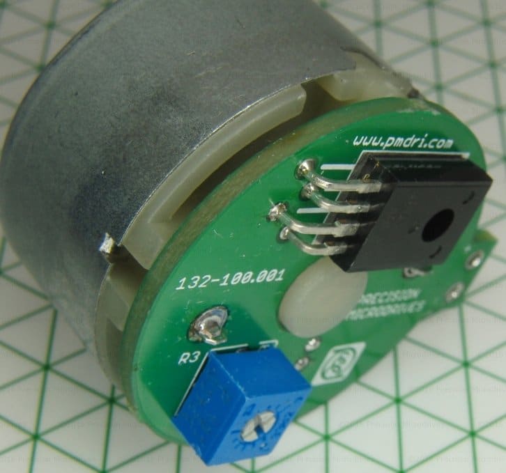
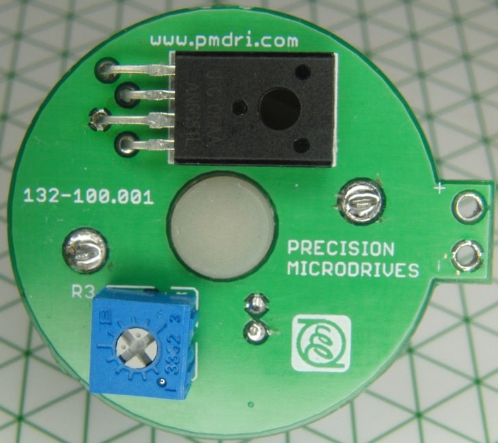
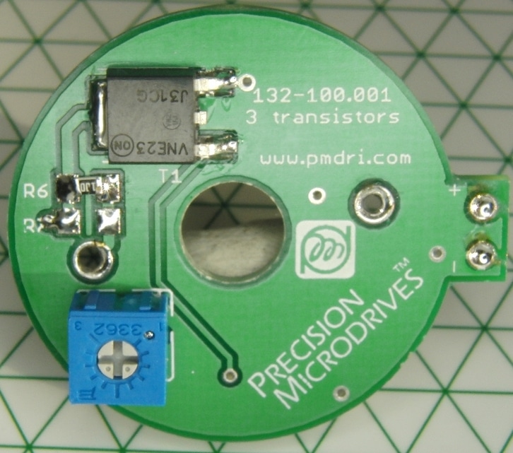
For example, using a standard 390 Ω value for R1 (a lower value reduces tendency to cause oscillation), we need to find values for series connection of R2 and R3. Let’s use the 132-100 DC motor and set a target speed of 2,400 RPM. First we need some of the technical details:
- Motor resistance, 𝑅𝑚=10Ω
- Input voltage for no load with speed of 2,400 RPM, 𝑉𝑚=3.87𝑉
- Current for no load with speed of 2,400 RPM, 𝐼𝑚=23𝑚𝐴
We can calculate the voltage drop on the internal resistance as:23𝑚𝐴×10Ω=0.23𝑉
and we can also calculate Vbemf as:3.87𝑉−0.23𝑉=3.65𝑉
In steady state when circuit is balanced, the equation for the circuit is:𝐼𝑚×𝑅𝑚+𝑉𝑏𝑒𝑚𝑓=𝑅1×(𝐼𝑅2𝑅3+𝐼𝑅2𝑅3+𝐼𝑚𝐾+𝑉𝑟𝑒𝑓
From this equation we can calculate the back EMF:𝑉𝑏𝑒𝑚𝑓=𝑉𝑟𝑒𝑓+𝑅1×(1+140)×𝐼𝑅2𝑅3
As we know from the datasheet Vref = 1V, so:𝐼𝑅2𝑅3=𝑉𝑏𝑒𝑚𝑓–𝑉𝑟𝑒𝑓𝑅1×(1+140)
For our motor we have:𝐼𝑅2𝑅3=3.64–1390×(1+140)𝐼𝑅2𝑅3=0.0051𝐴=5.1𝑚𝐴
With this value we can calculate the series resistance of R2 and R3:𝐼𝑅2𝑅3=𝑉𝑟𝑒𝑓𝑅2+𝑅3𝑅2+𝑅3=𝑉𝑟𝑒𝑓𝐼𝑅2𝑅3𝑅2+𝑅3=195Ω
We can use a constant standard resistor of 150 Ω plus a 100 Ω potentiometer, which gives us a range for fine tuning. The calculated values are only an approximation, in a real circuit the current of internal voltage reference source is also significant (between 0.8 – 2mA for AN6651), this will cause a change in motor current.
Adding a potentiometer allows the setup to adjust the speed and should be calibrated after some time, so the motor is at operating temperature to minimise the resulting shift in resistance.
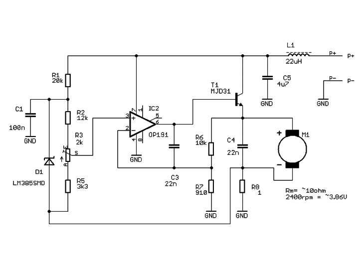
Speed Controller With Discrete Op-Amp
This is an improved version of our op-amp circuit above, using a dedicated IC. The main improvement is low voltage operation, thanks to the use of a low voltage bandgap reference. Using this discrete component minimises the size of the circuit, perfect for modern small enclosures.
In this circuit, the compensation voltage is taken from series resistor R8, whose value is less than motor internal resistance to reduce power losses. The second bridge leg is formed with R6 and R7. The ratio of these resistors should be the same as R8 and motor winding resistance. R8 can be chosen as a typical value, then R6 and R7 should be chosen for compensation of internal voltage drop. For stable operation, the factor of R7 / R6 should be greater than Rm / R8.
This circuit should be suitable for small motors with rated voltage 1V ~ 2V.
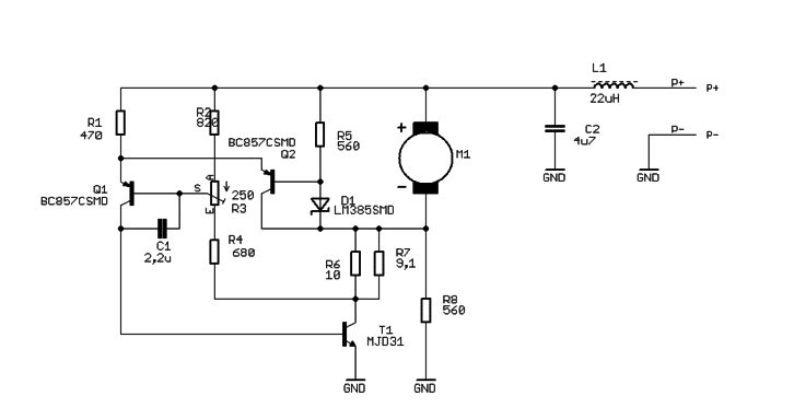
Speed Controller With Transistors
This inexpensive circuit is built with transistors to control motor speed, whilst it doesn’t offer the same accuracy as the op-amp it can be made extremely small and is useful for low-cost applications.
In this circuit, the voltage reference is 1.2 V and D1 works as a voltage reference. The motor back EMF is greater than reference voltage – dependant on the R2, R3, and R4 voltage divider:
- First, we need to set voltage divider factor, our reference voltage is 1.2 V and when the desired back EMF is 3.6 V the voltage divider R2, R3, and R4 should have a factor of: 3.61.2=3
- So we have a maximum range to fine tune the circuit, this should be done when potentiometer (R3) is in the middle position. Now we need to split the remaining value between each of the other resistors.
- When we know our voltage divider factor, choosing R6 and R8 is easy. We need to have the same ratio between the voltage divider and R6, R8, and motor internal resistance.
This circuit is designed for one constant speed, and changing the speed using the trimmer affects the speed compensation. So the trimmer should only be used to tune this circuit in very low-speed ranges. To use this circuit with wide speed setting range, we need to make some modifications:
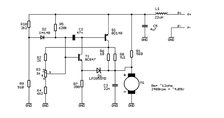
This circuit works on the same rules as the previous two transistor version, but the main improvement is increasing the gain for the reference voltage by transistor Q2. This allows us to use micropower bandgap voltage reference, which is more stable than standard diodes. Another improvement from adding Q2 is the temperature compensation of Vbe between Q1 and Q2 transistors.
Calculating this circuit starts from setting the back EMF voltage. In this circuit, the reference voltage is equal to LM385 – 2.5 V and voltage Vbe of Q2:𝑉𝑟𝑒𝑓=𝑉𝑏𝑔𝑟𝑒𝑓+𝑉𝑏𝑒=1.2𝑉+0.7𝑉=1.9𝑉
If we need Vbemf to be 3.8V, the voltage divider R2, R4, and R3 factor should be 2:1. Potentiometer (R3) is for fine tuning this voltage, but in this circuit changing speed using the trimmer will cause compensation change. So R3 is only for final speed tunning in a small range, say 5% or less, and should only be used to compensate the tolerance of other component values.
After setting this voltage divider, choosing R6 and R7 value is easy when we know motor internal resistance. The equivalent parallel connection of R6, R7, and motor resistance should have the same ratio as R2, R3, and R4 voltage divider (with the R3 potentiometer set in middle position).
Switching Mode Analogue Speed Controller
This application note describes a simple implementation of an analogue motor speed controller, based on a back EMF measurement and PWM drive signal.
When using PWM with a DC motor it is still possible to control the motor speed without any sensors. Using a typical low-cost driver with a single MOSFET, the back EMF can be measured when the motor is turning and the transistor is off.
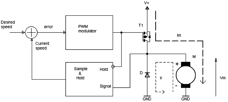
This controller consists of a PWM modulator, an output transistor, and a ‘Sample & Hold’ circuit (sometimes known as ‘follow-and-hold’ circuits). The PWM modulator has control input which enables the duty cycle to be varied. If unfamiliar it may seem complicated, but the general idea is fairly simple:
- when the transistor is ON, the supply voltage is connected to motor terminals, motor current Im flows through the motor, causing it to accelerate
- when the transistor is OFF, the motor acts as generator and Vm is equal to Vbemf, which is proportional to motor speed. The Sample & Hold circuit is triggered, which stores a sample of Vbemf in a capacitor
The summing node then calculates the difference between the desired speed and the current speed, as both are represented by a voltage (desired voltage and Vbemf, respectively). This error voltage is used to control the motor speed by increasing or decreasing the duty cycle in the PWM modulator.
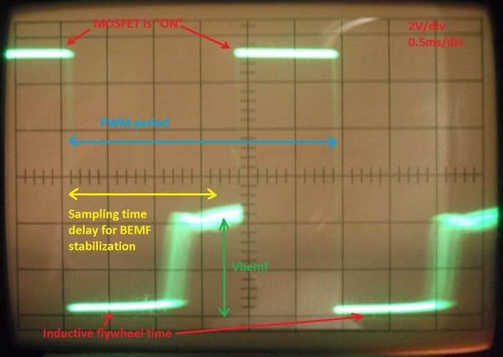
Due to the inductive nature of DC motors, measuring the back EMF is impossible immediately after turning the transistor OFF. When the transistor is switched a strong inductive spike is generated and the inductive recirculation current Ir flows by reversing diode. A short delay is necessary until the back EMF voltage becomes stable:
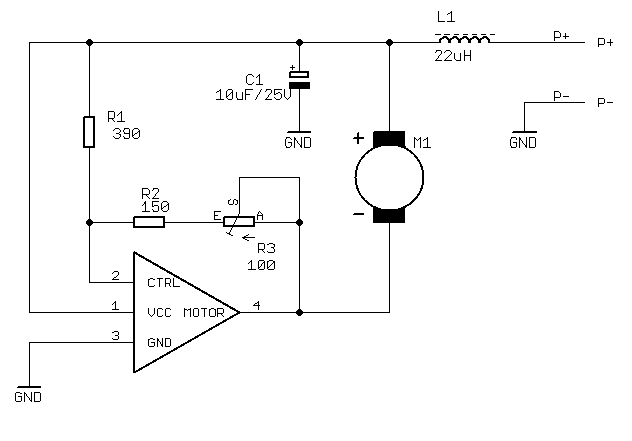
This method of control can be made using only analogue components or with a digital with a microcontroller. A practical implementation of a controller based on this method, and using the 132-100 DC motor, is shown below:
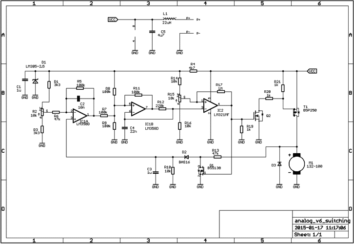
In this circuit, the voltage across R2 represents the desired speed, IC1A works as an error amplifier and PID controller.
The PWM modulator circuit is built with IC1B and IC2, where IC1B works as triangle wave generator with the frequency defined by R12 and C4.
IC2 acts as a comparator which compares triangle signal voltage from IC2 output with setting voltage from the R15 potentiometer. When the triangle signal voltage is lower than the voltage from R15 the comparator output is high and the motor is powered.
The Sample & Hold circuit is made by C3, R10, D2, Q1, R13. When the motor is powered by T1, Q2 is ON and the R13 and D2 node is shorted to ground, preventing it to make a sample when Vcc is applied to the motor. Diode D2 prevents the discharge of C3 when Q1 is ON.
When T1 is OFF, Q2 is also off and Vbemf can charge capacitor C3. The voltage on C3 is on the non-inverting input of error amplifier, IC1A. This amplifier subtracts the current speed voltage from desired speed voltage (set by R2 potentiometer). When the back EMF is increased, the output voltage on IC1A also increases – this shifts the triangle signal level up in proportion with the speed error. If the triangle signal level is increased, then the time when the output transistor is ON decreases, and PWM duty is also decreased.
This error amplifier work as a PID control circuit, where the gain is defined by 𝑅5𝑅5+𝑅10 and the time constant is defined by R5 and C2.
The Sample & Hold circuit is very simple because the sampling time is as long as the OFF state in the PWM duty cycle, so the sample voltage is directly dependent on the duty cycle. Also, it is less significant if the circuit is used to control an application that doesn’t use the motor’s full range of speed. It can be also reduced by choice, altering the values of R10, C3, and R13, which allow to change charge/discharge time of C3.
The range of PWM duty cycle change (from the applied error voltage) is defined by the relationship of R7 to R8||R9, however, because the Sample & Hold circuit is so simple this range shouldn’t be very wide.
This circuit is made to operate in the small band of PWM, the maximum PWM duty is reduced by the delay of the inductive load of the motor, and with the limitation of the Sample & Hold circuit this method shouldn’t be used for wide range of speed regulation.
This demonstrates the principle of operation, so for real-world use, it is strongly recommended that the simple Sample & Hold circuit be improved. For example, a circuit based on the inexpensive LF398 can provide a sampling time 10us.
In comparison with the negative terminal feedback analogue circuit, this method:
- reduces power losses
- could be more stable, as the temperature won’t affect the back EMF voltage (by changing the winding resistance)
However, it also:
- is not suitable for motors with high inductance
- has a narrow range of speed regulation
- has a tendency for oscillation
Newsletter
Sign up to receive new blogs, case studies and resources – directly to your inbox.

Sign up
Discover more
Resources and guides
Discover our product application notes, design guides, news and case studies.
Case studies
Explore our collection of case studies, examples of our products in a range of applications.
Precision Microdrives
Whether you need a motor component, or a fully validated and tested complex mechanism – we’re here to help. Find out more about our company.