Connecting external actuator (vibration motor) to the M20-200 Haptics Kit
Looking for our Haptics range? View our main Haptics hub here.
Introduction
Our haptic feedback evaluation kit is an inexpensive tool for everyone interested in implementing a vibration alerting or haptic feature into a project. It allows application engineers and designers to understand the performance of the various actuators that we produce. It can also be used by inexperienced users, who have just started working in the fascinating world of haptic feedback.
The M20-200 haptics evaluation kit is pre-fitted with 6 actuators of 4 different types, however, the range of motors we produce is far greater. In addition, customers frequently ask about using the haptics kit to drive motors that are already installed into their application prototypes. Our haptics kit is prepared for these tasks and requires only a few simple modifications that are covered below.
Connecting the actuator
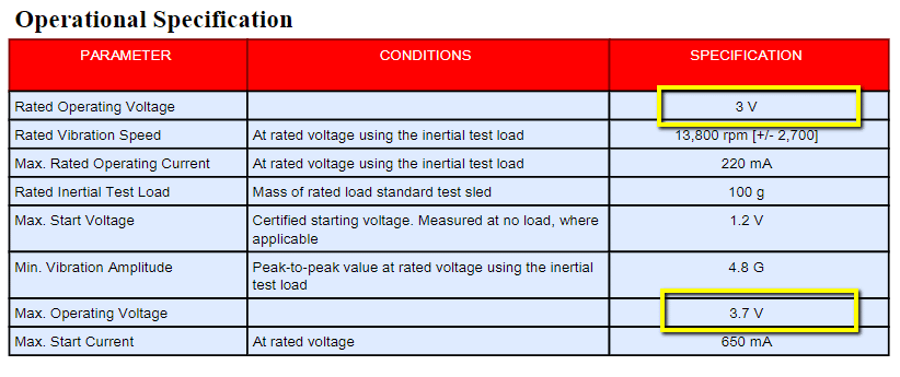
Any Precision Microdrives ERM and LRA motor/actuator with a rated drive voltage of less than 5V can be successfully evaluated with our haptics kit. In this case, we will use the ERM 307-103 9mm Vibration Motor 25 mm type.
To do so, the user needs to follow two simple steps:
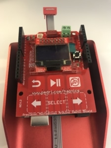
1. Disconnect the grey ribbon cable from the Haptic Grip
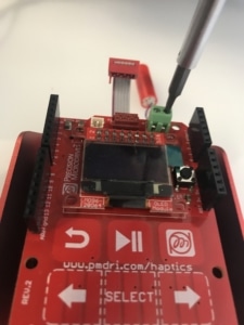
2.Attach the actuator to either the screw terminal (X3) or Molex connector (X2)
Updating the firmware
To connect an external actuator, you need to update the firmware of the haptic kit. This is an easy process and no coding experience is required.
The PMD haptic kit is based on the TI driver DRV2605L, and this driver runs an auto-calibration function before driving the motor. This means the driver needs to know what motor it is driving and model its characteristics in order to optimise the drive signal for crisp haptic feedback.
This autocalibration function needs several inputs, and two of them are intrinsically related to each motor. We are talking about the rated voltage and the overdrive voltage.
Two registers contain these values:
- RATED_VOLTAGE [7:0] in address 0x16
- OD_CLAMP [7:0] in address 0x17
In this case, we are using as an example of the ERM motor 307-103, whose characteristics are shown below.
The DRV2605L datasheet explains how to calculate these values. Fortunately, TI provides a spreadsheet that makes this task simpler. This configuration tool can be downloaded here.
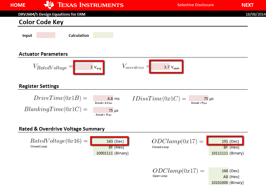
In the second tab “ERM/LRA Voltage Equations” we just have to input the rated and overdrive voltages and the spreadsheet will use the calculation methods that you can find in the DRV2605L datasheet. Remember to make sure you are using the correct spreadsheet, depending on if your actuator is an ERM or an LRA.
The decimal output values Rated Voltage (Close Loop) and ODClamp (Close Loop) need to be updated in the Evaluation Kit firmware.
To do so, the Development Mode and Engineering mode codes from our website can be downloaded here. Once that code is opened in Arduino, go to the motor.h tab.
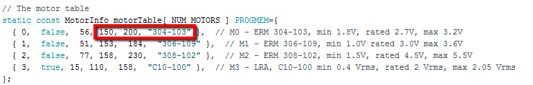
Choose one of the motors id to be updated, in this case, we will use the number 0 because we are going to connect an ERM. However, for ERMs, either the id 0, 1 and 2 will be ok. In case we would like to use an LRA, we would use the motor 3.
The values that we have calculated previously with the spreadsheet will be introduced here. The rated voltage (decimal value) where the ‘153’ is, and the Overdrive Voltage (decimal value) where the ‘191’. You can also change the part number you are connecting.
If you have decided to use the Development Mode, in line 53 of the DevelopmentMode.ino file, we need to select our motor id.
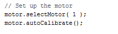
In our case, it will be motor.selectMotor ( 0 );. Remember, this needs to be consistent with the motor id we have chosen in the motor.h tab.
Conclusion
If you have followed the steps, you should be able now to play effects on your external actuator. In case you have decided to use the Engineering Mode, download the code to Arduino, after the modifications covered in this post. You will find more information in the user’s manual, under section 5.
Using the Development Mode is a useful way to start designing your new project and we encourage you to do that.
The main loop in the DevelopmentMode.ino is a great starting point to implement clicks, buzzes or ramps.
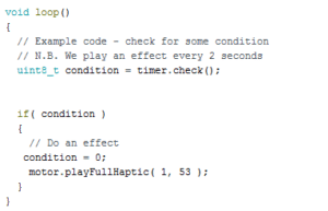
If you wish to play a specific effect, the correct library and effect need to be chosen within the playFullHaptic function.

Get in touch
Speak to a member of our team.
Motor catalogue
Looking for our products?
Reliable, cost-effective miniature mechanisms and motors that meet your application demands.
Newsletter
Sign up to receive new blogs, case studies and resources – directly to your inbox.

Sign up
Discover more
Resources and guides
Discover our product application notes, design guides, news and case studies.
Case studies
Explore our collection of case studies, examples of our products in a range of applications.
Precision Microdrives
Whether you need a motor component, or a fully validated and tested complex mechanism – we’re here to help. Find out more about our company.