Making A Haptic Device
Looking for our Haptics range? View our main Haptics hub here.
We decided to share the design considerations of our haptic feedback evaluation kit for a couple of reasons. Firstly, it highlights many of the great features of the kit. In addition, it is a useful exercise for those who are in the process of designing their own haptic device, even those who already have haptics and are looking to improve their performance may pick up a few tips.
There are four areas that can benefit from specific attention to improve their haptic performance. We look at each in turn, of course, if you have any specific questions feel free to contact us.
Mounting hardware and enclosure design
We discuss how to mount different vibration motors in several of our Application Bulletins. However, for a haptics device, it is more than just ensuring the motor is secure. It is also important to consider the direction of vibrations.
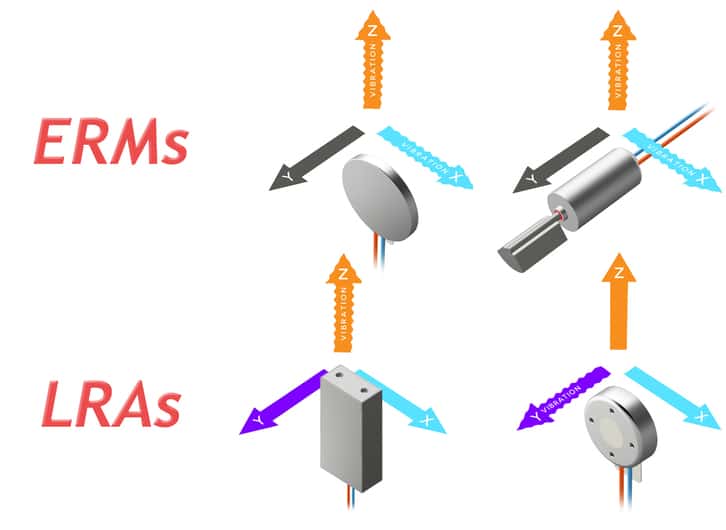
Vibration motors and linear resonant actuators produce vibrations in different directions depending upon their design. Furthermore whilst ERMs will vibrate in two axes, an LRA will only produce vibrations in one. This is due to the ERMs rotational behaviour which has movement in two axes, whilst the LRA will only move in two directions the one axis (hence the term ‘linear’). See the graphics below, for coin and cylindrical ERMs we experience vibrations in both the Z (orange) and X (blue) axes. Depending upon the LRA design, vibrations are either present in the Z or Y (purple) axis only.
For improved haptic feedback it is important to direct these vibrations towards the user. For example, a touchscreen should vibrate directly towards the user’s finger. For more examples with diagrams, see AB-014: Mechanical Layout of Vibration Motors for Typical User-Interfaces and Controls. We have compromised to find a balance between the most effective mounting direction and creating space to fit a variety of different actuators into the Haptic Grip.
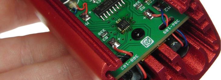
It is also essential the motor is held tightly to the enclosure, and if mounted on a PCB / internal bulkhead that this is also securely attached to the enclosure. As vibrations are repeated displacement, any gap between the vibrating motor and the enclosure will result in increased audible noise (like a rattling sound) and a decreased vibration amplitude. Overall, it can make the product sound poorly made and lessen the user experience. The evaluation kit has both SMD and a self-adhesive mounted LRA connected to the PCB in addition to leaded ERMs. The PCB has been carefully designed with supporting contacts to ensure that there is no movement between it and the outer plastic grip.
Note that certain materials can dampen vibrations. Flexible or soft foams and plastics will absorb some of the movement from the actuator, so you may need to compensate for this when deciding upon your ERM / LRA. The ERMs with power leads that are included in our evaluation kit have been mounted in heat-shrink to help fit and reduce audible noise. The DRV2605 has a few features to help compensate for any losses.
Haptics Actuator
Once you understand how you wish to mount your and the directions it should vibrate, you can start the selection process. Vibration motors will vary in form factor, physical size, rated voltage, etc., but there are a few product features that require specific consideration for haptic performance.
The best haptics actuators can be found in our Precision Haptics™ range. The ERMs and LRAs found in this range have been specially designed for advanced haptic feedback use, including quick start and stop times. They will all be tested with Immersion’s TS2000 criteria, qualifying them to be used with specially licensed Immersion software and associated drivers.
Other ranges are better suited for different applications, such as vibration alerting or mechanical aid. Visit the Pico Vibe™, Uni Vibe™, and Dura Vibe™ ranges on our vibration motors product guide page.
The vibration amplitude must be of a suitable level, remember we mentioned above that using flexible materials with the enclosure will dampen vibrations. This is also a consideration for devices that are used by operators who wear protective gloves or clothing. Also, consider which part of the body will feel the vibrations because fingertips and hands are much more responsive than thighs or chest.
In addition, the vibration frequency of the actuator can have an important role to play as higher frequencies attenuate more with padded clothing. For ERMs the vibration frequency is related to the speed of the motor and therefore varies with the amplitude, meaning a single haptic waveform can include multiple frequencies of vibration:
\* Vibration \: Freq \: (Hz) = \frac{Motor \: Speed \: (RPM)}{60} \*
However, for LRAs, the frequency is fixed to the resonant frequency of the unit. This allows the device to separate the vibration amplitude so it can be varied without impacting the vibration frequency.
There are several Haptic Characteristics that we test during our in-house quality processing, which we looked at in detail in the ‘What Makes a Good Actuator?’ section on the Adding and Improving Haptics page. These values attempt to characterise the motor for use in a haptic feedback application by measuring the typical response times of the unit. Also included on our datasheets are a wealth of information about the motor, such as their specifications and typical performance characteristics.
Electronics and Circuitry
To provide feedback, the device must have some kind of input. This could be a torque sensor on an electronic torque wrench or an internal input like a timer in a vibrating watch. It is most effective to handle these, possibly multiple, inputs with a microcontroller.
With the evaluation kit, we were most interested in allowing the user to experience a variety of haptic waveforms on different actuators. For this reason, we wanted to enable the user to easily select both the haptic waveform and which actuator it would vibrate. Therefore our inputs were fairly simple, all of the user interfaces is through a capacitive touchscreen on the Haptic Shield – although it is possible to attach external sensors and other components through the stackable headers.
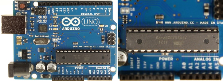
To operate the capacitive keypad and OLED display we used a microcontroller, Atmel’s ATmega168. Hobbyists will recognise this as the microcontroller used on the Arduino Uno. Arduino is an inexpensive and well supported open-source electronics prototyping platform.
Using a microcontroller not only enables advanced functionality in other areas of the device, such as driving LED displays, but makes it very easy to store and select advanced vibration outputs.
However, as microcontrollers cannot provide enough current to drive ERMs or LRAs there must be an additional driving circuit. Whilst vibration alerting applications can use a simple MOSFET to drive their ERMs, haptics really requires an H-bridge circuit as a minimum.
The best haptics devices use dedicated haptic driver chips. There is a range of these commercially available, each with different features. Using a driver helps protect the microcontroller and most allow the user to drive either an ERM or LRA, some even store the haptic waveform on-chip which frees memory in the microcontroller. We implemented the Texas Instruments’ DRV2605 in our evaluation kit.
The DRV2605 has a range of features that improve haptics performance, in the instance of our Evaluation Kit there were a few that stood out. First, it could drive both ERMs and LRAs which reduced our component footprint as we were able to use a single driver chip.
We were also able to take advantage of the 100+ haptic waveforms that are royalty-free and stored on the chip. This reduced our time spent designing and debugging as we did not have to create or store the waveforms on the microcontroller. Instead of using an I2C signal from the microcontroller we were able to simply select the desired vibration waveform and the DRV2605 handled the electrical signalling. Of course, the chosen waveform is actually dependant upon the input from the user. This feature is called the Digital Playback Engine.
In addition, the chip will automatically improve the haptic performance by handling techniques like overdrive and automatic braking. This means the haptic characteristics we listed in the Haptic Actuator section above will all be improved by the chip. In addition, the auto-resonance detection feature will always drive the LRA at its resonant frequency, which is extremely useful as the resonant frequency can shift depending on product age, temperature, orientation, etc. A slight discrepancy between the drive signal frequency and the resonant frequency (even a few hertz) can reduce the maximum vibration strength.
As the kit includes 4 different haptic feedback actuators which can be selected in the different user interfaces, or programmed using our DRV2605 Arduino Library.
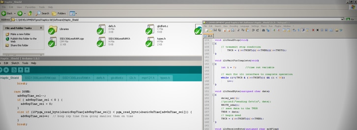
Software
After considering the actuator and drive circuitry, you can now look at improving the software in the microcontroller. This will greatly depend upon your choice of microcontroller and driver. For example, when using an H-bridge the control signals will come directly from the microcontroller, meaning the waveforms must either be stored on the microcontroller or memory.
If using a driver chip that supports PWM, then the waveforms can be stored as a series of duty cycles in a named array. This allows the microcontroller to easily store multiple waveforms that can easily be called by referencing the appropriate array.
In the case of our evaluation kit, we use an I2C bus to interface with the DRV2605 and select our vibration output. This freed the microcontroller to handle the user interface. Now the capacitive touchpad and LED screen enable the user to select a vibration waveform as the input, and the microcontroller simply receives this input and selects the corresponding waveform from the DRV2605’s onboard library to create a haptic feedback output.
For a closer look at the user interface, you will be able to consult an online version of the user manual for the evaluation kit when available.

Get in touch
Speak to a member of our team.
Motor catalogue
Looking for our products?
Reliable, cost-effective miniature mechanisms and motors that meet your application demands.
Newsletter
Sign up to receive new blogs, case studies and resources – directly to your inbox.

Sign up
Discover more
Resources and guides
Discover our product application notes, design guides, news and case studies.
Case studies
Explore our collection of case studies, examples of our products in a range of applications.
Precision Microdrives
Whether you need a motor component, or a fully validated and tested complex mechanism – we’re here to help. Find out more about our company.