AB-006
Mechanical Mounting For Vibration Motors To PCBs
Introduction
There are many methods for mounting a vibration motor to a Printed Circuit Board (PCB), each with its own advantages and disadvantages. Some techniques are specific to different types of motors, so whether you have already chosen a motor and are deciding how to mount it, or are starting from scratch take a look at our guide below.
This guide will help you evaluate different mounting methods and perhaps introduce some options you had not considered. If you are unsure which is best or would like further advice, please feel free to contact us. The different mounting techniques are split into four main groups, and each is discussed in turn:
- Solder Methods
- Glue and Adhesive Methods
- Fasteners and Clips
- Injection Moulded Mounts
We conclude the guide with a section highlighting some important considerations when securing the PCB to an enclosure.

Get in touch
Speak to a member of our team.
Motor catalogue
Looking for our products?
Reliable, cost-effective miniature mechanisms and motors that meet your application demands.
Solder Methods
Through-Hole Pins
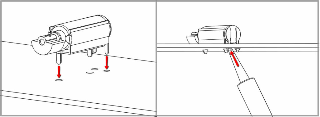
Some motors, such as the 304-100, have mounting pins on the body of the motor. These pins are placed through holes on the PCB and soldered in place. In our datasheets we provide accurate dimensions for the motor, including the mounting pins, to aid the PCB design.
Separate from the power connectors, these pins are designed to hold the motor in place and aid the mechanical integrity. The rigid connection also helps the transmission of vibrations from the motor to the PCB, which is in turn connected to the case.
The only drawback with thru-hole soldering is the footprint – no signal tracks can be run on the underside of the motor. If space is not at a premium then this may not be an issue, if it is, consider surface mount motors.
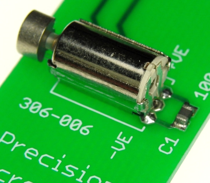
Surface Mount Reflow
Surface Mount Technology (SMT) is a common practice for many electronics manufacturers. It is similar to using through-hole pins, but solders the components directly onto the surface of the PCB. Again, our datasheets contain the appropriate Dimensional Specifications for PCB design.
These motors allow for easy retrofitting to products because they do not require any modification to the enclosure, and can be simply mounted on a PCB. Their small size means they can help with tight space requirements. EMC performance can be superior to leaded components because a suppression capacitor can be placed extremely close to the motor terminals. For large production runs, they are very labour efficient and can be supplied in reels for assembly.
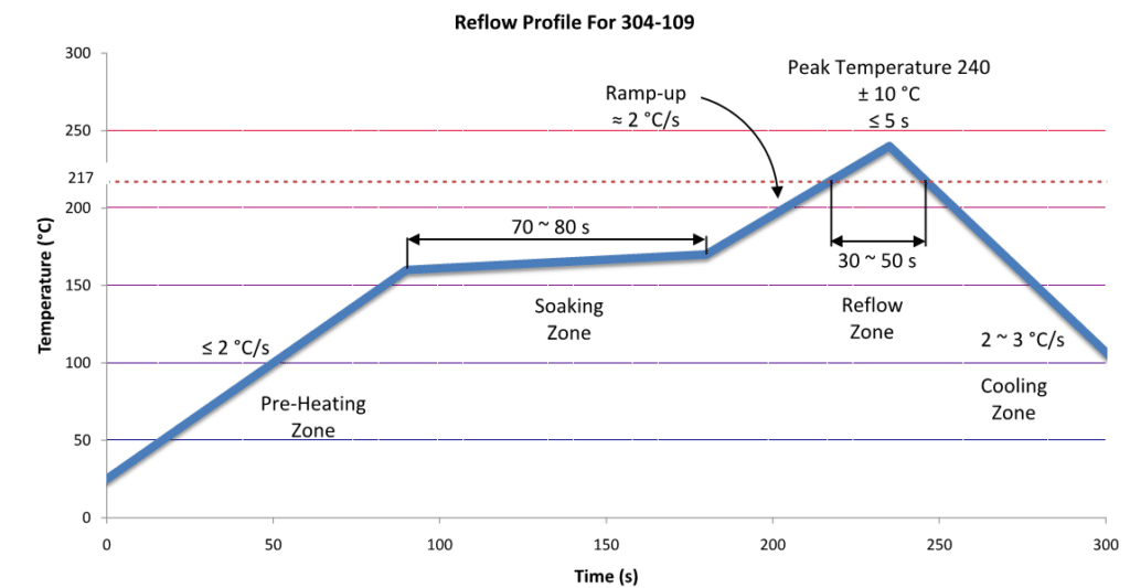
As for all SMT components, users must stick to the Reflow Temperature guide profile as they can be sensitive to heat. Whilst their small size makes them ideal for crowded PCBs, those requiring large vibrations may need a larger motor.
Glue And Adhesive Methods
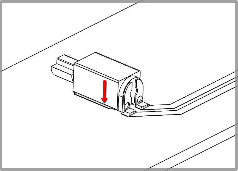
Adhesive Pad On Coin Motors
This is the simplest way to mount our coin or ‘pancake’ vibration motors and also applies to our Linear Resonant Actuators. All of these motors, for example, the 308-100, have an adhesive pad on the back to stick them directly to a PCB or another part of the enclosure.
These adhesive pads are simple and strong and do not require any additional brackets or accessories to secure them. Most coin vibrating motors have leads for flexible power connections, but some spring pad connector types are also available. Their low profile and easy mounting make them ideal for retrofitting to add vibration features to existing products or for last-minute design changes.
Adhesives For Non-Coin Motors
Many of our vibration motors are cylindrical and do not have through-hole pins or are SMT mountable. For these motors, it is possible to use an adhesive such as glue, epoxy resin, or similar product to mount the motor to the PCB or another part of the enclosure.
Due to its simplicity, this is a popular method for prototypes and experimenters. Also, suitable adhesives are widely available and generally inexpensive. This method supports leaded motors and motors with terminals, both allow for flexible mounting options.
Attention must be taken to ensure that the adhesive is strong enough to secure the motor. The strength of the adhesive can be easily improved with the correct application on clean surfaces. Please note a ‘low blooming’ adhesive with high viscosity (i.e. don’t use cyano-acrylate or ‘super glue’ – rather use Epoxy or hot-melt) is strongly recommended to ensure the substance does not enter the motor and glue the internal mechanism.
For extra protection, you may wish to consider our Encapsulated Vibration Motors, which are generally easier to glue.
Fasteners And Clips
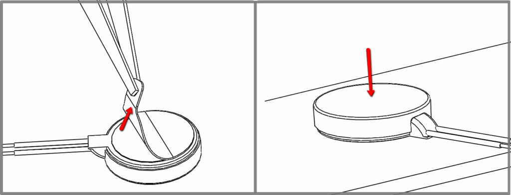
Cable Tied To Mount
This method is particularly useful if you are using a vibrating motor with an eccentric mass that rotates beyond the body of the motor, but it can also be used by other cylindrical vibration motors too. Placing the motor in a moulded or machined ‘cradle’, it is secured down using a cable tie which passes through the PCB.
This raises the motor from the PCB, allowing for large eccentric masses to rotate unimpeded, whilst requiring minimal adjustment, simply two holes for the cable to pass through. This is also a non-permanent method for mounting the motor, allowing for it to be removed or changed at a later date with no damage to the PCB.
It is important to machine a cradle that closely fits the motor as any movement for the motor will translate as a loss in vibration strength and produce a lot of audible noise. There may also be potential for the motor to work its way free if the cable is significantly loose.
To dampen harmonics (the audible noise), consider using hot-melt adhesive from a ‘glue gun’ to further secure the motor in place.
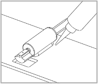
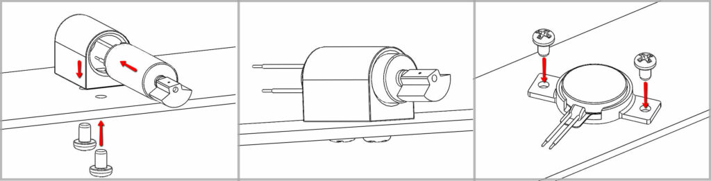
Screwed Inverted U
Using a similar plastic mount as the ‘cradle’ in the Cable Tied to Mount method above, the motor is secured to the PCB. Instead of a cable passing over the mount to secure it, screws can be used to attach the PCB to the housing.
This method supports a wide variety of cylindrical ERM motors. It may also be possible to completely house the motor such that no external moving parts are exposed. This method may be preferred to the Cable Tied Mount as screws are generally easier to use than cable ties.
As it requires screws to be passed through the PCB, tracks cannot run in this area. Also, the plastic housing will increase the space requirements, and therefore will not be suitable for circuits with low footprint availability.
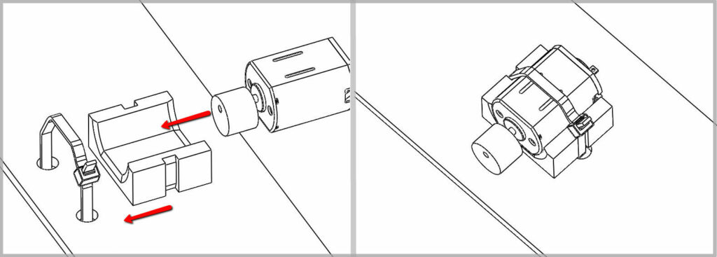
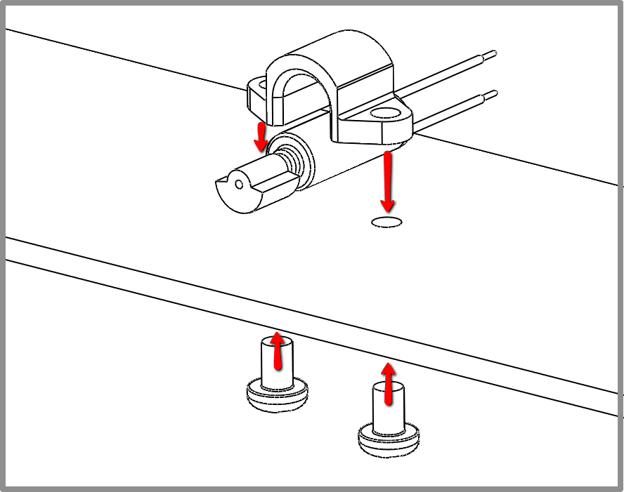
Clip Housing
‘P Clips’, or a mounting bracket, are a popular method for securing motors to surfaces, not just PCBs. They wrap around the motor and with two flat sections at the side (making a P shape) to screw through the PCB and are held in place with a screw. Other types of clips could be produced, such as an open frame which allows for the motor to be taken out and replaced (if a high usage duty cycle is expected you might be better of with a brushless vibration motor).
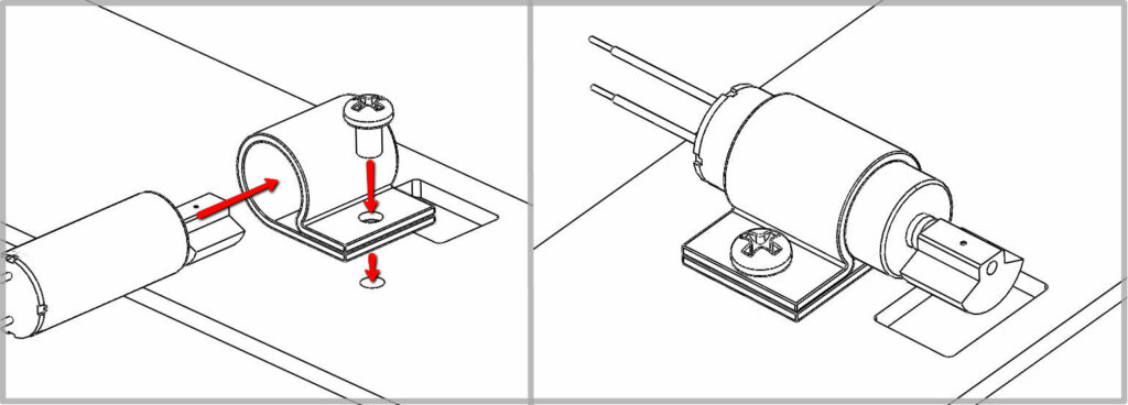
Clips can often accommodate a variety of motor sizes and are simple to use. They are also cheap and widely available from a variety of outlets. They can securely mount the vibration motor to the PCB and often only require one screw to hold the motor in place. As with all screw mounting techniques, the screw will take up space on each side of the PCB. Many clips are designed for larger motors or applications, so take care to ensure that the clip will not sit loosely around the motor’s body.
Remember to use a shake-proof washer or ‘grover’ with the screw – it is vibrating! Consider using Loctite 638 as well.
Injection Moulding Methods
Moulded Mounts
Moulded mounts are injection moulded plastic housings for the motor. This method holds the body of the vibration motor within the moulded plastic housing, which is then screwed to the PCB. The security of the motor in the housing may be improved using an epoxy or similar silicon filler as discussed in the Glue and Adhesives section above. Please note resins must be of ‘low-blooming’ type to avoid motor damage.
The moulded mount benefits from having a secure screw connection to the PCB and can provide enough space for a large eccentric mass to rotate. Similar to the Screwed Inverted U, the motor may be completely contained within the mould, removing external moving parts (for non-coin vibration motors). The use of screws means the motor can be easily removed or adjusted at a later date. In addition, as the moulds are designed for the vibrating motor they can be more secure than other methods (e.g. the side flanges of the illustrated coin motor mount).
However, the mould does add to the overall size of the motor unit, the height in particular. Also, the screws do not allow tracks to be run on the underside of the board, although these may only be a problem for certain vibration motor applications.
Spring Pad Enclosure Moulding
To secure the motor to a PCB, the moulding does not necessarily need to be screwed or secured to the PCB. Instead, the enclosure can act as housing for the vibration motor, which is then pinned to the circuit board. This is a common technique in mobile phones and other devices with minimal space to spare. Many of our vibrating motors have spring pad connectors, for example, the 304-108, which are perfectly suited for this mounting method.
The removal of connectors can help save space on the PCB and vibrations are transmitted directly through the enclosure, improving the overall performance.
The only complication is that this method requires greater design of the enclosure, and may therefore not be suitable for some applications or those who do not have access to the resources. This also makes it more difficult to retrofit vibration functionality into the design.
Newsletter
Sign up to receive new blogs, case studies and resources – directly to your inbox.

Sign up
Discover more
Resources and guides
Discover our product application notes, design guides, news and case studies.
Case studies
Explore our collection of case studies, examples of our products in a range of applications.
Precision Microdrives
Whether you need a motor component, or a fully validated and tested complex mechanism – we’re here to help. Find out more about our company.