When LRA’s don’t behave as expected (Part 2 of 2)
This blog post is part two of a 2-part series. Part one was a quick recap of how LRA’s work and how they are driven by dedicated driver ICs. This part is about what happens when the LRA’s don’t work entirely as expected with selected driver IC’s, how to diagnose this, and what to do about it.
Introduction
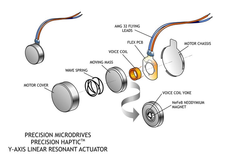
In part one of this blog post we explained that to get the most performance from an LRA, we need to drive it at its resonant frequency. The individual resonant frequency of an LRA will vary within a high-volume manufacturing batch, due to variances in manufacturing tolerances, and also with environmental factors. We, therefore, need to use a driver IC that will track the resonant frequency and adjust the driving signal frequency and amplitude accordingly.
We have been generally been referencing Texas Instrument LRA drivers for our examples and haptic feedback evaluation kit, because they’re easy to use, and were the first to be readily commercially available. These drivers have fuelled growth in the LRA market, and they work by sensing the back EMF (BEMF) of the LRA’s and adjusting the drive signals appropriately.
Mostly this works very well, but every now and then we have to debug an application problem from a customer, and it’s never quite as simple as it first appears…
The #1 Application problem with LRAs…
99% of problems relating to the use of LRA’s in the real-world come down to unacceptable levels of noise or ‘rattle’. The LRA’s are vibrating often very well, but they’re rattling or noisy. We as the LRA manufacturer get the blame.
The rattle comes from the internal mass hitting the inside of the case. There are only two possible root causes for this. A defective LRA (unlikely) or an LRA being driven too hard by the driver (much more likely). So, why would the LRA be overdriven?
LRA Start-up (open loop) vs BEMF Managed Resonance (closed loop)
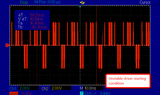
Most LRA drivers have two function states. The first state is an open-loop start-up in which there is no measurable BEMF from LRA. In this state, the driver must drive the LRA with parameters (frequency and amplitude) that are ‘guessed’, until the LRA’s BEMF can be measured, and the drive loop closed. To reduce the time taken to establish a reliable BEMF feedback signal, the LRA driver will often use maximum drive parameters.
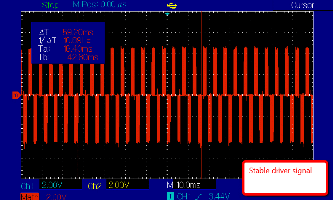
Once a reliable BEMF signal is measured the LRA driver can enter into its second state which is closed-loop BEMF Managed Resonance. In this 2nd stage, the driver will sense the BEMF from the LRA coils and adjust the driving parameters accordingly. Typically this will mean adjusting the frequency of the drive signal to match the resonant frequency of the LRA, and throttling back on the amplitude to a long-term sustainable level.
In some cases, it is possible that the closed-loop state is never achieved, for example, because the BEMF can’t be measured from the LRA. A consequence of that is that some (older design) drivers will continue to drive the LRA in the open-loop state with maximum drive amplitudes. These can be quite a bit higher than the equations provided by the driver IC manufacturers would lead designers to expect, which are all based on closed-loop control.
For example, the newer DRV2605 and DRV2625 have sets of registers that can be used to configure the drive parameters, and in particular their maximum values. However, older drivers such as the DRV2603 do not. The DRV2603 is cheaper, as a result, but it is also possible for this driver IC to become stuck in the open-loop start-up drive stage if BEMF can’t be reliably detected.
The Consequences of Being Stuck in a Continuous Open Loop Start-up Drive Stage!
Most machines don’t function well when overdriven for extended periods of time, and LRA’s are no different. There are two consequences of being driven in open-loop start-up modes for extended periods of time:
- Noise. The LRA internal mass may hit the top and bottom of the casing, particularly if the inertial load of the application device is light, e.g. a 50g remote controller or smartwatch. Note that the low device mass may also be a reason that the BEMF wasn’t correctly measured in the first place (see below).
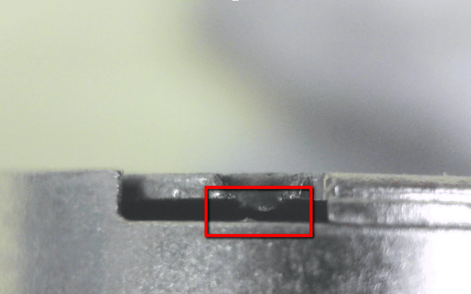
- Fatigue. Being overdriven for extended periods of time will cause fatigue in components like the mainspring that holds the mass inside the LRA. More likely is that the main spring to chassis weld joints will start to fail and cause the mass to move further than designed. In that case, it definitely will hit the top of the LRA casing and cause a significant clattering noise.
Why Can’t the Driver Measure the LRA Back EMF?
There are two potential causes here, but one is much more common.
- (Uncommon) In measuring the LRA BEMF, the driver assumes a certain coil resistance which is often specified in the driver datasheet or application notes. If the LRA’s actual coil resistance is significantly different, then potential divider made between the LRA and the driver sensing circuit may not produce sufficiently strong signals for the driver to measure. In practice, we have not seen this problem ourselves, as our coil resistances are close to what Texas Instruments (TI) expect, however, we have heard this being a problem with other manufacturers LRA designs.
- (Common) Drivers and LRA’s are mass-produced for the mobile phone market. Mobile phones tend to weigh around 100 ~ 150 grams. The BEMF measured will depend on the mass of the application device. Therefore, if the mass of the application device is low, for example as would be expected with a small keyfob remote or smartwatch ~50g, then the resulting BEMF value in the non-powered parts of the drive cycle is lower as well. This is because, with a lower inertial mass, there is less energy within the system and therefore less energy to convert into BEMF.
Conclusions
Using LRA’s designed for mobile phones for a low mass application may be the only option due to price/IP/volume availability. However, when using a cheaper driver without register control such as the DRV2603, beware that it may get stuck in an open-loop start-up driving mode. This may consequently cause the LRA to be overdriven, resulting in internal component fatigue and/or wanted noise.
A simple solution is to use a driver with full control over the drive signals. Newer drives such as the DRV2605 and DRV2625 have registers that can be set via the I2C interface and allow designers to prevent prolonged driving in potentially damaging open-loop drive configurations.

Get in touch
Speak to a member of our team.
Motor catalogue
Looking for our products?
Reliable, cost-effective miniature mechanisms and motors that meet your application demands.
Discover more
Resources and guides
Discover our product application notes, design guides, news and case studies.
Case studies
Explore our collection of case studies, examples of our products in a range of applications.
Precision Microdrives
Whether you need a motor component, or a fully validated and tested complex mechanism – we’re here to help. Find out more about our company.