The Practicalities of Reversing DC Motors
Introduction
At the end of last year, Doug wrote a blog post about the basics of reversing DC motors. Since a number of customers have asked us to advise about this recently, we expand upon this topic with some practical tips. If you’re not interested in the theory, skip to the end for our practical conclusions section.
Are DC motors Reversible?
In short, yes. If you reverse the voltage to the motor, it will rotate in the opposite direction. The reasons for this are given in the earlier blog post ARE DC MOTORS REVERSIBLE?
But we need to take a closer look at what else is happening here…
The Motor Field and Brush Geometry
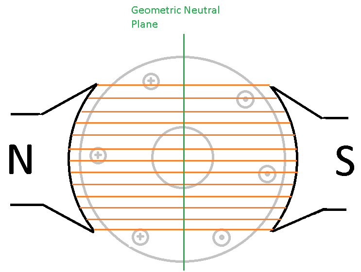
Permanent magnets produce a constant magnetic field where magnetic flux lines are parallel to each other. Perpendicular to the magnetic flux, and cutting through its middle is an axis called the magnetic neutral plane. When the motor is stationary, this is the same as the geometric neutral plane, which is shown in the figure below in green. The magnetic neutral plane is significant because when the motor is rotating there is no back EMF generated as the armature crosses this point.
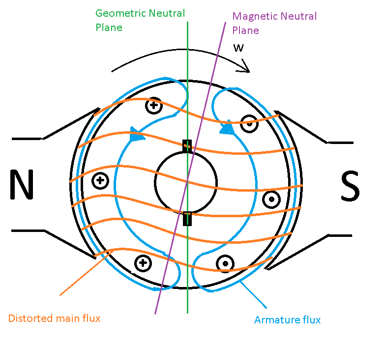
Now when the motor is powered it is rotating, and current is flowing through the armature. This produces a magnetic field that interacts with the permanent magnet’s magnetic field to create the rotating force known as torque. What may not be so obvious is that the magnetic field from the armature distorts the magnetic field produced by the permanent magnets. This, in turn, causes the magnetic neutral plane to shift away from the geometric neutral plane as shown in the figure below. We can say that the magnetic neutral plane is either advanced or retarded depending on whether it comes before or after the geometric neutral plane.
The faster the motor rotor spins, the further the magnetic neutral plane moves from the geometric neutral plane. The motor torque is highest when the back EMF is lowest, and the back EMF is lowest at the magnetic neutral plane. This gives us an opportunity to maximise torque by making sure that the magnetic neutral plane is right slap bang in the middle of the commutator segment connecting the currently energised armature coil.
Simplified, this means that by moving the position of the commutator relative to the armature windings, we can increase the motor torque. This technique is called commutator advancement and helps increase the motor performance.
Running a Motor with Advanced Commutator in Reverse
So now that we have the understanding that motors can have an advanced commutator to increase performance, what happens when the same motor is run in reverse?
Well, the magnetic neutral plane is symmetrically flipped about the geometric neutral plane axis, meaning that the middle of the commutator is now on completely the wrong side of the geometric neutral plane axis with respect to the point of lowest back EMF. This, in turn, means that the motor torque is lower when the motor is run in that direction, which will also likely affect the speed of a loaded motor.
Practical Conclusions
Summing up then, here are some practical points to consider:
- You can run DC motors in both directions.
- Some DC motors will run with better performance in one direction than the other, due to commutator advancement built into the motor when it was designed.
- Motors from Precision Microdrives are generally wound ‘neutral’, that means with no commutator advancement. This, in turn, means that mostly they should run with similar performance in both forward and reverse directions.
- Motor directions are given on the datasheet as well as which terminals are + and -.
- Running the motor in the forward direction is likely to make it last longer. This is because the brushes are now being ‘dragged’ over the commutator rather than ‘pushed’ over the commutator. This, in turn, tends to reduce brush vibration, which then reduces the amount of arcing that can take place between the brush and commutator surfaces. Since arcing causes the brush and commutator surfaces to erode and oxidise, less arcing means better quality motor commutation for longer.

Get in touch
Speak to a member of our team.
Motor catalogue
Looking for our products?
Reliable, cost-effective miniature mechanisms and motors that meet your application demands.
Discover more
Resources and guides
Discover our product application notes, design guides, news and case studies.
Case studies
Explore our collection of case studies, examples of our products in a range of applications.
Precision Microdrives
Whether you need a motor component, or a fully validated and tested complex mechanism – we’re here to help. Find out more about our company.