AB-021
Measuring RPM from Back EMF
Introduction
Measuring the speed of a motor can be an important requirement for some applications. For example, DC and gearmotors that are moving loads may require close monitoring or adjustment of the output speed.
External sensors are typically used for speed measurements, such as Hall sensors with a magnet mounted on the shaft, or transoptors with a slotted plate (also mounted on the motor shaft).
These sensors can give accurate information about motor speed, required space and increase the cost of parts. Sometimes it’s impossible to add an external sensor to a motor due to space or pricing restrictions.
We can properties of the motor itself for a low-cost RPM measurement, which is based on the back EMF. In fact, the back EMF is a very important measurement for haptic feedback chips when driving vibration motors and LRAs.
We’ll explain a sensorless method, where we use an Analogue to Digital Converter which is onboard our microcontroller that generates the PWM drive signal. We haven’t included any additional measurement chips or components.

Get in touch
Speak to a member of our team.
Motor catalogue
Looking for our products?
Reliable, cost-effective miniature mechanisms and motors that meet your application demands.
What is back EMF?
Back electromotive force (back EMF, BEMF) is a voltage that appears in the opposite direction to current flow as a result of the motor’s coils moving relative to a magnetic field. It is this voltage that serves as the principle of operation for a generator.
The back EMF is directly related to the speed of the motor, so knowing the value of back EMF allows us to calculate the speed of that motor.
Let’s review the brushed DC motor equivalent circuit:
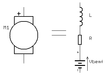
We can represent the motor as a series connection of resistance, inductance and the back EMF voltage source. It is this voltage source that we want to measure.
When the motor is powered from constant DC voltage and not running (i.e. rotor is stalled, or motor is starting) the only resistance to current flow is coil resistance. The inductance impedes the current when the voltage is not constant DC, for example when powered from a PWM source.
This resistance and inductance are very small by design, which explains why the start-up current of a DC motor is typically a few times greater than in normal operation. If the motor is stalled then the high current can destroy windings unless it is limited by external circuitry.
The role of the inductance is a little complicated to explain, so we will start by reviewing the equation which describes current through the coil 𝐼=𝑑𝑉𝑑𝑡.
The inductance tries to preserve constant current in the circuit, so it only has an effect when there is a changing voltage i.e. 𝑑𝑉𝑑𝑡≠0. The inductance reduces the current’s rate of increase when a voltage is applied to the coil, then when that same voltage is disconnected the inductance generates a high voltage in an attempt to maintain the steady-state current value.
If a voltage is applied to a stalled motor, the inductance will reduce the current for a short time, however, the current will quickly reach a steady state value. When the current is non-changing, the inductance of the coils has no effect and the only limit to the current in the resistance of the coils.
Once the motor starts to rotate, the coils are switched on and off by the commutator. Immediately after a connection is made, the inductance of the coils slows down the rising current. After disconnection, the inductance generates high voltage spikes.
When using PWM to control a motor, we observe voltage spikes when the gating transistor is switched off. This partly explains why high-frequency PWM can exhibit non-linear control characteristics, because a low duty-cycle at high frequency creates a narrow pulse in time. The rate of change of current is too small, and the current can’t rise fast enough to reach its steady state value.
In a stall condition, the coil inductance has much less influence on current than the coil resistance.
When the motor is spinning the back EMF has a much bigger influence on current than resistance and inductance.
As the back EMF is generated from the rotor is moving through the magnetic field generated by the permanent magnets, the back EMF is directly proportional to the motor speed, and the motor voltage constant. The motor voltage constant includes parameters like magnetic field strength which are also constant.
𝑏𝑎𝑐𝑘𝐸𝑀𝐹=𝑅𝑃𝑀𝐾𝑣
Back EMF always acts to reduce the changing magnetic field through the coils. It does so by generating a voltage which opposes the supply voltage, thus reducing the current.
In ideal DC motor where R=0 and L=0, and RPM is constant with no load, back EMF will be exactly the same as the supply voltage.
Back EMF vs RPM on the 106-002 DC Motor
We can calculate the back EMF by measuring the current in steady state with no load and comparing it to a calculated value for the stall current. We can then use this value with the no-load speed and the motor’s constants to calculate the speed for the given back EMF.
The 106-002 has the following properties:
Rated Voltage: 3V
N/L Current: 20mA
N/L Speed: 23,000 RPM
Coil resistance: 16 Ω
If the motor is stalled and is powered with rated voltage, the current through the windings is limited only by resistance:
𝐼𝑠𝑡𝑎𝑙𝑙=𝑉𝑠𝑢𝑝𝑝𝑙𝑦𝑅
3𝑉16Ω=187.5𝑚𝐴
When the motor is rotating the back EMF works against the power voltage and thus reduces current to 20mA. Therefore the size of the back EMF is equal to the reduction in current times the terminal resistance:
𝑉𝐵𝐸𝑀𝐹=(𝐼𝑠𝑡𝑎𝑙𝑙–𝐼𝑁/𝐿)×𝑅
Substitute 𝐼𝑠𝑡𝑎𝑙𝑙 from above:
𝑉𝐵𝐸𝑀𝐹=(𝑉𝑠𝑢𝑝𝑝𝑙𝑦𝑅–𝐼𝑁/𝐿)×𝑅
𝑉𝐵𝐸𝑀𝐹=𝑉𝑠𝑢𝑝𝑝𝑙𝑦–(𝐼𝑁/𝐿×𝑅)
𝑉𝐵𝐸𝑀𝐹=3𝑉–(0.02𝐴×16Ω
𝑉𝐵𝐸𝑀𝐹=2.68𝑉
The back EMF constant 𝑘𝑏 is the relationship between the back EMF and the speed (converted to radians per second). At no load:
𝑘𝑏=𝑟𝑎𝑑𝑠−1𝑉𝐵𝐸𝑀𝐹
𝑘𝑏=(23,000×2Π)60)2.68𝑉
𝑘𝑏=2408𝑟𝑎𝑑𝑠−12.68𝑉
𝑘𝑏=898.7
And Speed Constant 𝑘𝑠
𝑘𝑠=1𝑘𝑏
𝑘𝑠=1898.7
𝑘𝑠=0.001113
Remember these are both based on calculations from the back EMF – not the applied voltage (so appear inverted to the normal calculations for DC motor constants).
As the relationship is linear we can use these constants to calculate the speed of the motor for a measured back EMF.
Let’s check the values we have calculated, if the motor was turning at 12,500 RPM (1309 rads^(-1)) what would the back EMF and current be?
𝑘𝑏=𝑟𝑎𝑑𝑠−1𝑉𝐵𝐸𝑀𝐹
𝑉𝐵𝐸𝑀𝐹=𝑟𝑎𝑑𝑠−1×𝑘𝑏
𝑉𝐵𝐸𝑀𝐹=1309×0.001113
𝑉𝐵𝐸𝑀𝐹=1.46𝑉
𝐼=𝑉𝑠–𝑉𝐵𝐸𝑀𝐹𝑅
𝐼=3𝑉–1.46𝑉16Ω
𝐼=0.096𝐴
Now reading the Typical Performance Chart on the 106-002, at ~96 mA we can see the speed is ~12,500 RPM. We now have a way of calculating the back EMF and then in turn the speed of the motor from the measured current draw.
Simple Hardware for BEMF Measurement
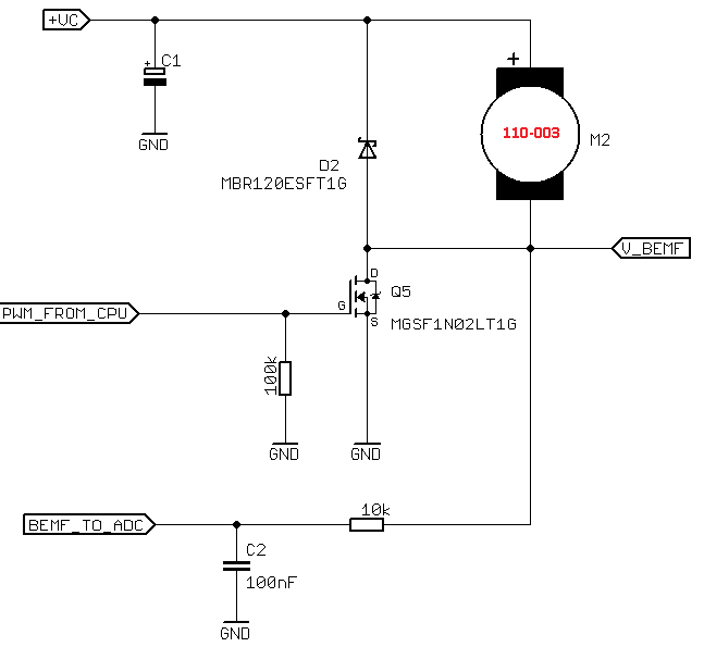
Let’s construct a simple circuit for measuring the back EMF of a DC motor. We’ve chosen the 110-003 with these parameters:
- Rated Voltage: 1.3V
- No Load Current @ 1.3V: 65mA
- No Load Speed @ 1.3V: 9500rpm
- Coil resistance: 3.2Ω
- 𝑘𝑏 = 0.00158
We will use an ATmega168A microcontroller which will generate PWM signal for the 110-003 motor.
The MOSFET is switching the motor on by connecting motor negative terminal to ground. When the transistor is ON current from power supply flows through the motor to ground, and we can’t measure the back EMF.
When the transistor is OFF the motor negative terminal is floating, and back EMF measurement is possible. For measurement, we will use an Analogue to Digital Converter on the microcontroller, in addition to an oscilloscope so we have a visual representation of the behaviour.
Note that the back EMF voltage is in reference to the power supply but our ADC measure voltage is in reference to ground. When motor is stopped and back EMF = 0 our control voltage Vs = Vc. A lower value on the ADC input represents a high back EMF.
The oscilloscope is also connected to point Vs to measure back EMF with reference to ground as well as the ADC. Set the PWM frequency to 100Hz, although this is very low it gives more time for ADC conversion. Also note the supply voltage is 4.2V and rated voltage for 110-003 is 1.3V, therefore the PWM duty cycle shouldn’t be greater than 40%.
The 110-003 motor is started with a duty cycle of 12.5%, we can check the circuit through the oscilloscope:
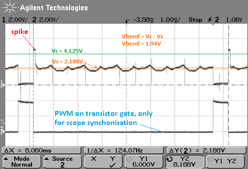
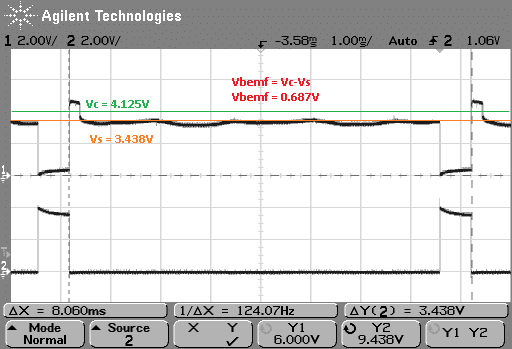
When the motor load increases (which we do manually), the speed decreases and back EMF signal is also lower.
Back EMF Speedometer with Microcontroller
So now we measure the RPM using Atmega168, making use of the analogue to digital converter.
The measurement accuracy depends upon the microcontroller’s max PWM frequency and maximal pulse width. The ADC in the Atmega168 takes 13 ADC clock cycles, which is dependant upon the system clock and prescaler settings – it can’t be greater than 200kHz.
We use an internal RC clock 8MHz, so our maximal clock value is 125kHz (= 8MHz / 64). This gives an ADC clock period 8µs and minimal conversion time 13 * 8µs = 104µs.
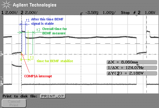
The interrupt service routine also takes another few microseconds and some time is needed for the back EMF to stabilise, so we don’t measure the inductance spikes. Accounting for everything, the determine minimal pulse width must be greater than ~120µs for an 8MHz clock.

For PWM control we use Timer 1 as PWM generator and enable OCIE1A interrupt to trigger ADC measurement. For simplicity, ADC conversion is started immediately after OCIE1A interrupt but one or more of the first samples are rejected. This makes our routines simpler and gives time for back EMF stabilisation.
Here’s example code for the Timer 1 configuration on the ATmega168:
//------------------------ Init Timer 1 as PWM --------------------------------------------
void InitTimer1(void){
	TCCR1A = (1<<COM1A1)|(1<<WGM11); // Toggle OC1A on compare 9Bit
	TCCR1B = (1<<WGM12); // 9bit
	TCCR1B = (1<<CS10)|(1<<CS11); // clk/64  8Mhz/64 = 125kHz    125kHz/9bit = 244Hz
	TIMSK1 |= (1<<OCIE1A); // on compare to trigger ADC
	OCR1A = 10; // initial pwm value
}
And the Analog to Digital Converter set-up routine:
//---------------------------- Init ADC ------------------------------------
void InitADC(void){
	ADCSRA  |= (1<<ADEN) | (1<<ADPS2) | (1<<ADPS1);
	// enable ADC, prescaller  8000000 hz / 64 = 125kHz
	ADMUX   |= (1<<REFS0);  // reference AVCC
	DIDR0    = (1<<ADC0D);  // disable digital input
}
For better accuracy, it’s good to average the measurement from a few samples, so our RPM reading frequency will be lower. This is important when using a PID controller for motor speed control, which can all be achieved with H-bridge as the output stage.
If you’re interested in seeing the full code, it’s available to download. Although it is originally written for the 103-001, there is nothing that constrains it to this model and can easily measure the speed of other motors. The results are sent using the USART to another device, of course, you may want to use the values directly on the ATmega168!
The only thing to note is that if you are using the PWM to power a motor from a different (and much higher) voltage source take special care that the back EMF won’t be too high for the ADC. Otherwise, you may end up damaging your microcontroller.
Newsletter
Sign up to receive new blogs, case studies and resources – directly to your inbox.

Sign up
Discover more
Resources and guides
Discover our product application notes, design guides, news and case studies.
Case studies
Explore our collection of case studies, examples of our products in a range of applications.
Precision Microdrives
Whether you need a motor component, or a fully validated and tested complex mechanism – we’re here to help. Find out more about our company.