
Technical resources
Articles, news and design guides
This resources section is where you can find product application notes, technical videos, design guides, news and case studies.
Search resources
Motor catalogue
Looking for our products?
Reliable, cost-effective miniature mechanisms and motors that meet your application demands.
PRECISION MICRODRIVES POSTS
Featured resources
Application notes
- AB-005: Electromagnetic Compatibility For Vibe Motors
- AB-006: Mechanical Mounting For Vibration Motors To PCBs
- AB-008: Vibration Motor Best Practices From Mobile / Cell Phones
- AB-007: Mechanical Mounting For Vibration Motors To Bulkheads
- AB-011: Electrical Techniques For Using Different Power Sources
- AB-010 : Mounting Vibration Motors To Flexible Materials & Clothing
Case studies
Technical posts
- Haptic Feedback Applications With Vibration Motors
- PCB Mounted Vibration Motors
- VAB-03: How Do LRAs Work?
- Vibration Alerting Applications
- Spur Versus Planetary (Epicyclic) Gear Types
- Positioning Actuators With DC Gearmotors
- Medical Applications With Vibration Motors
- Medical Applications For DC Gearmotors
Application notes
-
VAB-01: Introductory Gear Equations

The video below is based on Application Bulletin 024: Introductory Gear Equations. It covers the basics of meshed gears, including
View Post
-
AB-032: DC Motors – Voltage Vs. Output Speed Vs. Torque

The relationship between voltage, torque and output speed is a common topic of discussion between our customers and Precision Microdrives’
View Post
-
AB-025: Using SPICE To Model DC Motors

SPICE (Simulation Program with Integrated Circuit Emphasis) is an open source program for simulating electrical circuits. It enables engineers to
View Post
-
VAB-03: How Do LRAs Work?

In addition to covering the basics, we point out some of the advantages that LRAs have over their ERM counterparts
View Post
-
VAB-02: How Do Vibration Motors Work?

This VAB introduces how ERM vibration motors work, including how they create vibrations and what determines the vibration frequency and
View Post
-
AB-008: Vibration Motor Best Practices From Mobile / Cell Phones
The mobile phone industry is a huge market, in which vibration motors are an established component. Now almost every device
View Post
Case studies
-
Wearable fall detection aid

A robust vibration motor used to detect a fall, and connect the wearer to their emergency contacts.
View Case Study
-
PPE respirator hood system

A bespoke shrink wrapped vibration motor and mounting solution used in the notification system.
View Case Study
-
Digital medication management device
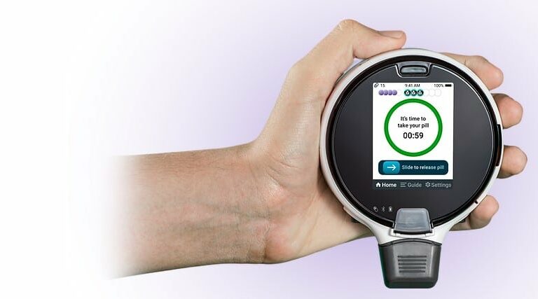
A digital medication management device for chronic disease patients taking controlled drugs, that sends reminders and feedback to their care
View Case Study
-
Electronic powered ball valve

Gear motor mechanism solution for a remotely operated electronic water ball valve used in isolated areas of the world.
View Case Study
-
Touchscreen ECG monitor

Touchscreen ECG monitor with integrated haptic feedback to provide a crisp ‘button pressing’ sensation when used.
View Case Study
-
Handheld blood gas testing device

Handheld blood gas testing device delivering lab-quality results at a patient’s bedside. Uses a miniature gearmotor and encoder to ensure
View Case Study
Technical videos
-
VAB-02: How Do Vibration Motors Work?
This VAB introduces how ERM vibration motors work, including how they create vibrations and what determines the vibration frequency and
View Post
-
VAB-03: How Do LRAs Work?
In addition to covering the basics, we point out some of the advantages that LRAs have over their ERM counterparts
View Post
-
VAB-01: Introductory Gear Equations
The video below is based on Application Bulletin 024: Introductory Gear Equations. It covers the basics of meshed gears, including
View Post
Newsletter
Sign up to receive new blogs, case studies and resources – directly to your inbox.
